Circuit design of a photodiode

Thread Starter

pooya_b

Joined Feb 25, 2021
59
Hello

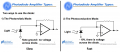
I am designing a circuit for a photodiode. I want this photodiode to be able to work at high speeds. To do this, I used the SFH2704 photodiode made by OSRAM company.

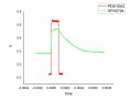
The problem I have now is that when I connect the photodiode directly to the oscilloscope, the fall time decreases slowly, which is not the case with the commercial photodiode called the PDA10A2 from THORLABS, which has an internal amplifier. This means that the excitation source does not have much fall time, but the SFH2704 photodiode shows that there is too much fall time. I put the pulse diagram for the two photodiodes along with the information of both photodiodes.

What circuit do you suggest to solve this problem?1.jpg2.jpg
 

Attachments

ericgibbs

Joined Jan 29, 2010
18,766
hi pooya,
It appears the scope lead impedance/capacitance is loading the PD.
You need a Fast OPA on the output of the PD
What is the PD normally driving into.?

E
BTW: The PDA is a much faster device than the SFH
 
Last edited:

schmitt trigger

Joined Jul 12, 2010
868
To realize the PD’s maximum speed (and they can be pretty fast), you require a transimpedance amplifier.

Analog devices has a very useful online design tool:

tools.analog.com/en/photodiode
 

Thread Starter

pooya_b

Joined Feb 25, 2021
59
hi pooya,
It appears the scope lead impedance/capacitance is loading the PD.
You need a Fast OPA on the output of the PD
What is the PD normally driving into.?

E
BTW: The PDA is a much faster device than the SFH
I did not connect anything and connected directly to the oscilloscope, but in the future I want to connect an analog converter to ADS 820 digital.
 

Audioguru again

Joined Oct 21, 2019
6,673
Your schematic is missing but you appear to be using the photodiode as a slow solar panel where it makes a small current when there is light. Then it is slow. A fast circuit has a reverse voltage across the photodiode as assumed in the datasheet which reduces the built-in capacitance across the diode causing it to be fast as it conducts when there is light.

I agree that the capacitance of your oscilloscope cable and probably the capacitance of rows of contacts and wires all over the place on a solderless breadboard are slowing down the signals.
 

Thread Starter

pooya_b

Joined Feb 25, 2021
59
Your schematic is missing but you appear to be using the photodiode as a slow solar panel where it makes a small current when there is light. Then it is slow. A fast circuit has a reverse voltage across the photodiode as assumed in the datasheet which reduces the built-in capacitance across the diode causing it to be fast as it conducts when there is light.

I agree that the capacitance of your oscilloscope cable and probably the capacitance of rows of contacts and wires all over the place on a solderless breadboard are slowing down the signals.
Can you give me a circuit design for this?
 
Can you give me a circuit design for this?
I already indicated how you could design one, but you have chosen to ignore the advice.

If anybody here provides you with a complete schematic, we don’t know whether the specified components will be available to you, whether we are exceeding your budget, or whether it meets your performance requirements.
 

Thread Starter

pooya_b

Joined Feb 25, 2021
59
I already indicated how you could design one, but you have chosen to ignore the advice.

If anybody here provides you with a complete schematic, we don’t know whether the specified components will be available to you, whether we are exceeding your budget, or whether it meets your performance requirements.
Unfortunately, I was not able to access the site you mentioned.
If you can give me a complete schematic I will find similar pieces.
But the biggest thing on my mind is why is the fall time of this photodiode so high? According to the manufacturer, it is about nanoseconds.
 

Thread Starter

pooya_b

Joined Feb 25, 2021
59
Is that volts on the Y axis of the SFH2704 chart?
And this is the output from the photodiode without an amplifier?
Yes, this is a photodiode output without an amplifier.
I connected the photodiode directly to the oscilloscope probe and it showed me the output.
My biggest problem is the high fall time of this photodiode.
 

Thread Starter

pooya_b

Joined Feb 25, 2021
59
I already indicated how you could design one, but you have chosen to ignore the advice.

If anybody here provides you with a complete schematic, we don’t know whether the specified components will be available to you, whether we are exceeding your budget, or whether it meets your performance requirements.
Unfortunately I could not log in to the site for some reason I could not log in now
Thank you very much.
 
Top