 Facebook
 Google
 GitHub
 Linkedin
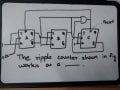
Do u think the circuit is correct.See from the circuit if the complimented output of 1st f//f is 1 and second normal output is 0.Then whats the one of the input of and gate.The two outputs wires are merged is that correct?
Attachments
-
 34.5 KB Views: 44


