Can you check if this buffer circuit is correct?

Thread Starter

sonohe

Joined Jan 11, 2025
58
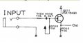
I have created a buffer, copied from the Boss MT pedal buffer, and added a trimmer to the output as well. I measured the in and outgoing signal, it seems to work, but there are 2 things I would like to have clarified before I plug this into my soundcard:

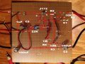
1. On the layered image, where you can see the back and the front of the vero board at the same time, I marked two stripes with green X. They are the stripes of the Drain and Source of the J112 transistor. Those are the two stripes where the meter beeps when I check if there is touching between the soldering and the stripes. Other stripes are okay, but those two beep. When I remove the transistor the beep stops. So either the beeping is normal, or every time I solder it, the soldering touches the adjacent stripe. It is normal that the signal can jump like that between the S and D of that transistor?

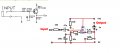
2. Maybe me measurements were wrong, but it seems if I turn the trimmer to max, there is no reduction on the output. Maybe I interpreted it wrongly, but isn't it the case that the outgoing signal should be reduced even without the trimmer, and the trimmer just adds more reduction?

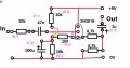
Sorry that the values are backwards in the plan, I had to mirror it before I started building.

buffer-panel-3md.jpg

layered.jpg
 

MrChips

Joined Oct 2, 2009
34,626
Circuit schematics is the language of electronics.
You need to provide the schematics before anyone can even look at this.
 

crutschow

Joined Mar 14, 2008
38,316
Haha, I am glad I could solder this one together as a total outsider.
So you did the design all in your head(?).
Well, that's interesting work as an outsider, but if you want to be an insider and get our review of your circuit, you need to draw a schematic. :rolleyes:
 

Thread Starter

sonohe

Joined Jan 11, 2025
58
What is the transistor? In your first post it appears to be a 2N???? but in the schematic above it is a 2SK184.
2N3819 was suggested to be used. I ordered it, but the pinout sheet was incorrect. Actually what I received had this written on it: JCJ112 T11. Someone checked, and suggested this pinout: https://www.onsemi.com/pdf/datasheet/j111-d.pdf
This one seems to work. Originally this circuit included the 2SK... transistor in Boss, but it is not really available here where I am, that's why a substitute was suggested.

Also in the beginning, a pad by resistors was suggested for the output. The story behind: we took the active buffer from the Boss, and checked the pad values in the Marshall 8080 amp, that is used in the circuit before the FX Loop In in that amp, and that's why the resistors are there on the drawing I sent. Later we concluded we need more reduction (on the marshall it is also there, besides the default pad, you can switch on extra reduction with a button.) We added a trimmer instead. So the resistors gone, but the trimmer is there instead.

Unfortunately I have no more access to the drawing with the trimmer. It was sent to me but I don't find it. I used it however to design the vero board plan that you see above.
 

Ian0

Joined Aug 7, 2020
13,097
The J111 might not be the best substitute for the 2sk184. The GS cutoff voltage is up to -5V, cf the 2sk184 less than -1.5.
J112 (which I assume is what JCJ112 T11 actually means) is closer, and I have often used J113 as a front-end for guitar amplifiers.
 

boostbuck

Joined Oct 5, 2017
1,032
The 113 is marginally ok, but surely not much headroom with any of them given the ref at 4.5V (1/2 battery voltage from the 10k/10k divider)?

1768293723458.png
 

Thread Starter

sonohe

Joined Jan 11, 2025
58
The 113 is marginally ok, but surely not much headroom with any of them given the ref at 4.5V (1/2 battery voltage from the 10k/10k divider)?
You mean with the original 2sk184GR the headroom will be more?

Originally the circuit I built looked different:
55100.png

The problem with this was that my guitar distorted with this circuit. The Vpp of my guitar is 3.2V. I built this circuit here on the image, replacing the 2SK with 2N3819. The result was that the lower half of the signal was clipped at 0.8V. And the circuit turned out to be improperly biased. Maybe if I put the 2SK into the circuit that you can see here, the clipping would not occur? In reality this circuit in the Boss has more parts, it has an AC powered segment as I remember. Some people said that due to the lack of that in my circuit, the construction became unbiased. Not sure if this is correct. But now as you mention the bigger headroom with the other transistor, maybe this simple version could work, too. What do you think?
 
Top