As the voltage source changes you get a step change in the voltage at V1. But after that you have an RC circuit that is charging/discharging with a 14 ms time constant, which is a lot longer than the 1 ms dwell time of the source waveform at each level, so you end up with a good approximation to a linear ramp.
It's caused by the limited low frequency response of the capacitor as it provides current through the diode clippers.
As the capacitor charges when providing this current the voltage across the capacitor increases, giving the tooth saw voltage waveform.
A larger capacitor would reduce this drop but there's no particular advantage to doing that.
It would be a good exercise for you to analyze the circuit in steady state (say beyond 20 ms) and figure out the response over the course of one cycle.
Sorry about reopening the post, but I was testing in multisim and the only thing the diodes are doing is limiting the voltage, instead of getting a sinve wave of 377mV I get 100mV or less.
I'm refering to the last circuit crutschow posted.
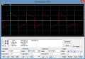
1 K and 1 uF is a time constant of 1 ms, so there should be considerable sag in a 5 ms period - as shown in your images. Wally's circuit time constant is four times larger, with much less sag.
1 K and 1 uF is a time constant of 1 ms, so there should be considerable sag in a 5 ms period - as shown in your images. Wally's circuit time constant is four times larger, with much less sag.
Yeah I just checked the output, it will also take more time to stabilize, converting that to a sine wave (pic below).
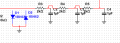
Just one more question, I think I understood why it gets centered, I mean a montage like that will make the voltage, after the capacitor, drop to zero, so I guess since it's a square wave, it will oscilate around zero. If it the resistor was first, it would start at zero and grow up until 5 V and oscilate there, right? And what is R1 doing in this montage?
 Facebook
 Google
 GitHub
 Linkedin