When the square wave is 50% on and 50 % off, then you may use a C-R network.
If it is not 50/50, you can subtract 2.5 Volts using an opamp adder circuit.
When the square wave is 50% on and 50 % off, then you may use a C-R network.
If it is not 50/50, you can subtract 2.5 Volts using an opamp adder circuit.
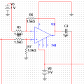
Use a 9V supply.
Create a 4.5V bias point by using a voltage divider with two 10kΩ resistors.
Use this to bias your input signal. Use a 1μF coupling capacitor. This will give a time constant of 5ms.
Use a 9V supply.
Create a 4.5V bias point by using a voltage divider with two 10kΩ resistors.
Use this to bias your input signal. Use a 1μF coupling capacitor. This will give a time constant of 5ms.
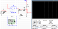
I tried to bias the square signal, can't get it to work.
I only can get the flip flop to output 5V (in this simulation), so I reduce that to 1V before the capacitor, after that the signal gets all screwed up.
You're right. It can't unless you cheat and use AC coupling.
In my opinion, the simplest way to bypass all that nastiness is to determine how much current your load needs when the output signal swings max negative and to use a negative supply which can supply that current.
If this is for your divide by 2 audio circuit, the output will be going between 0V and 5V in a somewhat random fashion so I don't see that the initial settling time of the RC circuit is a significant factor.
You are unlikely to hear the effect.
If this is for your divide by 2 audio circuit, the output will be going between 0V and 5V in a somewhat random fashion so I don't see that the initial settling time of the RC circuit is a significant factor.
You are unlikely to hear the effect.
+1
Agreed. We are showing you how to bias the input to ½ supply voltage.
Will this work to shift musical notes to a lower octave? I don't think so.
The way to do this is to use a DSP (digital signal processor) and do the frequency shift digitally.
This allows you to do other effects such as adding chorus.
If this is for your divide by 2 audio circuit, the output will be going between 0V and 5V in a somewhat random fashion so I don't see that the initial settling time of the RC circuit is a significant factor.
You are unlikely to hear the effect.
Just affraid that it will mess with my amp, but I guess those values won't be high enough. I mean everytime I play a note, that effect happens, so it might saturate (clip the signal) or something.
+1
Agreed. We are showing you how to bias the input to ½ supply voltage.
Will this work to shift musical notes to a lower octave? I don't think so.
The way to do this is to use a DSP (digital signal processor) and do the frequency shift digitally.
This allows you to do other effects such as adding chorus.
There are dedicated charge pump ICs that can turn +9V into around -8 V with a lot less effort and noise than a traditional switching regulator. Since you don't need for the negative voltage to be regulated and the current requirement is very low, a 555 plus 6 external components (1 R, 2 D, 3 C) will be fine for this. Once you have an opamp powered by +/- V, the waveform can be shifted a fixed DC amount and will stay put no matter what the duty cycle or frequency, with no startup offset.
 Facebook
 Google
 GitHub
 Linkedin