CD40106BE Oscillator Not Working HELP!

Thread Starter

PandaHero23

Joined Jun 16, 2016
19
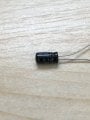
I wanted to make an oscillator out of a cd40109be chip so i looked up some tutorials on how to do it, i followed the tutorials and made sure i got everything right. but when i plunged a speaker in to the output and to ground nothing happened, so i used an LED but still nothing. I'm using a 9v battery to power the circuit on a breadboard and i got the chips from texas instruments via amazon. i am new(ish) to electronics so I'm probably doing something wrong, any ideas? thanks! :) heres some pictures of the circuit (there is also more information after the pictures):
IMG_0540.jpg IMG_0541.jpg
The red alligator clip is going from the output of the inverter into the positive input of the speaker and the white alligator clip is going to ground and is connected to the negative input on the speaker (the speaker is an Adafruit 3inch speaker) heres the tutorial i followed: http://hackaday.com/2015/02/04/logic-noise-sweet-sweet-oscillator-sounds/
 

jpanhalt

Joined Jan 18, 2008
11,087
Put a 0.1 uF decoupling capacitor (ceramic) as close as you can across the "positive" and "negative" leads.

Ground your unused inputs.

John
 

AlbertHall

Joined Jun 4, 2014
12,345
Standard loudspeakers are very low resistance (less than 10 ohms). That is much too low for the chip to drive and it will stop the oscillator dead. Try connecting the speaker through a small capacitor (perhaps 1uF?).

Also the capacitor in your picture looks like an electrolytic which will probably be too big to make an audible tone. What value is it?
 

Thread Starter

PandaHero23

Joined Jun 16, 2016
19
Standard loudspeakers are very low resistance (less than 10 ohms). That is much too low for the chip to drive and it will stop the oscillator dead. Try connecting the speaker through a small capacitor (perhaps 1uF?).

Also the capacitor in your picture looks like an electrolytic which will probably be too big to make an audible tone. What value is it?
its an electrolytic 0.1uF compositor
 

Thread Starter

PandaHero23

Joined Jun 16, 2016
19
Not sure what a compositor is but it definately looks like an electrolytic which makes it unlikely to be 0.1uF?

Can you tell us what's written on this capacitor?

You need something like a 0.1uF polyester capacitor.
opps, autocorrect lols. i checked the capacitor and it says its 0.1uF, heres a picture:
 

Attachments

dl324

Joined Mar 30, 2015
16,846
i did get an LED to light up with the output but no oscillation.
With 10KΩ and 0.1uF, I calculate a frequency of around 600Hz. Too fast for you to see the LED blink.

Show how you had the LED connected. If you loaded the oscillator, you'd change the frequency.
 

GopherT

Joined Nov 23, 2012
8,009
@PandaHero23

That chip is a hex inverter, to prevent loading the oscillator with your LED, put the output of your oscillator to the input of a second inverter (on that chip). Light your LED with the second inverter.

Also, put a 470 to 1k resistor in series with that LED because you may damage the chip if you don't limit the current flowing out (an LED does not limit current).
 

dl324

Joined Mar 30, 2015
16,846
I'm using a 100kohm resistor
It's 10K brown-black-orange; 100K would be brown-black-yellow.

You should have a current limiting resistor for the LED and you should use one of the other inverters to buffer the oscillator so you don't load it and change the frequency.
 

Thread Starter

PandaHero23

Joined Jun 16, 2016
19
It's 10K brown-black-orange; 100K would be brown-black-yellow.

You should have a current limiting resistor for the LED and you should use one of the other inverters to buffer the oscillator so you don't load it and change the frequency.
so in the end, how would the circuit look on a breadboard?
 

GopherT

Joined Nov 23, 2012
8,009
so in the end, how would the circuit look on a breadboard?
It should look like this.

Your resistor looks like a 10k, not 100k. If you don't have a yellow band, 100k resistor, then you'll definitely need a bigger cap. I think your 0.1F will be flashing 100x per second (100hz) and you won't tell if it is on or off by sight (you'll need a scope or signal counter).

Use a cap in the range of 10u to start out with a 100k resistor. Adjust parts from there.

As I mentioned above. Put a buffering, extra, inverter between RC network and LED. Also use the current limiting resistor on the LED.

See below


image.jpg
 
Last edited:

Bordodynov

Joined May 20, 2015
3,177
GopherT.
Attention!
Input pins CMOS logic should be connected (3A,4A,5A,6A). In this case, they can be connected to ground or to the power supply.
In the opposite case, the consumption current will be not determined. Although the circuit will operate.
 

Alec_t

Joined Sep 17, 2013
14,280
The LED without a series resistor is too great a load for the IC and prevents oscillation.
Pins 3,5,9,11,13 of the 40106 IC are presently unused gate inputs. Connect all unused inputs to ground (or to the +ve supply rail), as Bordodynov says. CMOS circuits behave erratically if input pins are left floating.
 

GopherT

Joined Nov 23, 2012
8,009
GopherT.
Attention!
Input pins CMOS logic should be connected (3A,4A,5A,6A). In this case, they can be connected to ground or to the power supply.
In the opposite case, the consumption current will be not determined. Although the circuit will operate.
Thanks for the "heads up". Fixed.
 

dannyf

Joined Sep 13, 2015
2,197
I did a quick sim for you. the oscillator does about 15ms periods -> 600Hz. So even if the oscillator is working, your eyes wouldn't be able to tell - the led looks constantly lit.

You can use a resistor to isolate the led from the chip's output, or since you have unused gates, you can use one of them to buffer the output then no need for that resistor.

Alternatively, use an led with high forward voltage, like a blue / white led. It helps with low supply as well.
 
Top