Cascaded 3-stage Amplifier

Thread Starter

Mattes

Joined May 13, 2019
6
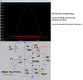
I am trying to design, build a test a 3 stage amplifier consisting of a class AB output stage and 2 common emitter stages to amplify a 20mVptp input to an 8Vptp output. R load is an 8 ohm speaker with a 12V supply.

The class AB design is done and completed. I have calculated an input impedance of ~6.5k ohm (not sure if this is correct).
The current stage 2 works in simulation and in practice (albeit less gain, getting a 7.4Vptp output). However my calculations here did not take into account the input impedance of the 3rd stage.
The first stage works perfectly in simulation but barely amplifies anything in practice. (I am assuming this is because of the input impedance of the rest of the circuit).

upload_2019-5-13_20-2-20.png

My question/s here are:
1) Is my calculation for the output impedance of the 3rd stage correct?
2) How should I be calculating the resistor values of the common emitter stages while taking the input impedance of the following stage into account?
 

Thread Starter

Mattes

Joined May 13, 2019
6
1) Is my calculation for the input impedance of the 3rd stage correct?* Correcting myself here since I can't edit posts yet.
 

BobTPH

Joined Jun 5, 2013
8,813
Why did you use such a low collector resistor on the first stage? Since this is handling very small signals it should be much higher, maybe 1K to 10K. Then biasing resistors can be increased as well, raising the input impedance.

Bob
 

Thread Starter

Mattes

Joined May 13, 2019
6
Why did you use such a low collector resistor on the first stage? Since this is handling very small signals it should be much higher, maybe 1K to 10K. Then biasing resistors can be increased as well, raising the input impedance.

Bob
When you say the biasing resistors can be increased do you mean for the first or second stage? If it's in the first stage how would raising the input impedance on the input help?
 

Thread Starter

Mattes

Joined May 13, 2019
6
Taking your suggestions, I have calculated some new values and significantly increasing the biasing resistors. Would you say these are more suitable values?

upload_2019-5-13_22-28-3.png
 

Audioguru

Joined Dec 20, 2007
11,248
None of your calculations or measurements are shown.

Your circuit is extremely old using capacitors for coupling instead of DC coupling. Also it will sound horrible since its output has no overall negative feedback to reduce distortion to be extremely low.

The coupling capacitor values are all wrong for audio.

The resistor values for the 1st and 2nd transistors are way too low.

I simulated the 1st transistor with its load:
 

Attachments

BobTPH

Joined Jun 5, 2013
8,813
if you need 8V out from 20mV in, the gain required is 8 /0.020 = 400.

Without getting into negative feedback just yet, you should arrange for each of the first two stages to have a gain of 20. The output stage has no voltage gain as it consists of two emitter followers.

Making each stage amplify by a moderate 20 and biasing the transistors correctly to get about V+ / 2 as the output with no signal will reduce the distortion. After you do that we can talk about negative feedback to reduce the distortion by another order of magnitude.

Bob
 

Thread Starter

Mattes

Joined May 13, 2019
6
None of your calculations or measurements are shown.

Your circuit is extremely old using capacitors for coupling instead of DC coupling. Also it will sound horrible since its output has no overall negative feedback to reduce distortion to be extremely low.

The coupling capacitor values are all wrong for audio.

The resistor values for the 1st and 2nd transistors are way too low.

I simulated the 1st transistor with its load:
Unfortunately this assignment has to be done without negative feedback. I agree the output is going to be horrible the scope here is just to get it to 8Vptp.
The simulation you have done with the load is the gain I should be getting, but in reality it's much, much less.
Are there any threads/tutorials you suggest looking at for how to properly bias common emitters? I can't seem to get the hang of it.
 

Audioguru

Joined Dec 20, 2007
11,248
The voltage gain will be very low if the collector and emitter pins of a transistor are swapped.
Your teacher and a modern text book should teach you how to properly bias a transistor, not me and not tutorials.

You also need to learn the simple calculation for the value of a coupling capacitor and how much load resistance to use.
 

MrAl

Joined Jun 17, 2014
11,389
Hi,

Another point is that one of the concerns is distortion. Placing a bypass capacitor directly across the only emitter resistor makes the stage less linear. To remedy this, place another resistor in series with that resistor/cap combination as that keeps at least some pure resistance in series with the emitter which keeps the stage more linear.

Numerous other issues :)
 

Audioguru

Joined Dec 20, 2007
11,248
"Unfortunately this assignment has to be done without negative feedback." An unbypassed emitter resistor produces negative feedback.
Then it will have as much distortion as is possible. Its gain is controlled by overloading each high gain transistor.
Maybe the teacher also does not know anything about it.
 

Thread Starter

Mattes

Joined May 13, 2019
6
Thank you for your suggestions. I am calculating new values taking a Vb of 1.5V, Ic of 2mA and Vce of 6V. Making sure not to completely bypass Re.
My final question here is how to calculate the input impedance of the third stage. I understand I have to take the small signal equivalent model.
This is my calculation thus far: Rin = (18k//18k)//({2n3904 hfe * bd139 hfe + 2n3906 hfe * bd140 hfe} * {re1 + re2} + 8)
re being 25mV/10mA
Rin = 8.2k ohms
Is this correct?
 
Top