 Facebook
 Google
 GitHub
 Linkedin
Hi,
I am purchasing this kit https://www.aliexpress.com/item/32921546222.html?spm=a2g0o.detail.0.0.5c767fffO0SQYr&gps-id=pcDetailBottomMoreThisSeller&scm=1007.13339.169870.0&scm_id=1007.13339.169870.0&scm-url=1007.13339.169870.0&pvid=f5f0e6cf-c3a2-4c09-82f8-be721241bf09&_t=gps-id cDetailBottomMoreThisSeller,scm-url:1007.13339.169870.0,pvid:f5f0e6cf-c3a2-4c09-82f8-be721241bf09,tpp_buckets:668#0#131923#18_668#888#3325#11_668#2846#8116#2002_668#2717#7558#101_668#1000022185#1000066058#0_668#3468#15609#236
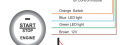
I want to however replace the push start button this kit comes (labeled "original" in pics attached) to another style push start (labeled "p3" in attached pics). The issue I have is the "original" push start button connects to a 10 pin input on the control unit however the push button I want to use (the "p3") only has 4 wire connector. See pictures attach of the "original connect wire" and the 4 pin connector shown in the "p3" pic and the "p3 connect wire".
My question is would it be possible to get the p3 to work instead of the original switch it comes with?
I have also attached pictures of the "10 pin input" on the control unit as well as the "circuit diagram" of the 10 pins on the control unit which highlight wat each pin is used for.
I would really appreciate help in this. Thank you in advance
I am purchasing this kit https://www.aliexpress.com/item/32921546222.html?spm=a2g0o.detail.0.0.5c767fffO0SQYr&gps-id=pcDetailBottomMoreThisSeller&scm=1007.13339.169870.0&scm_id=1007.13339.169870.0&scm-url=1007.13339.169870.0&pvid=f5f0e6cf-c3a2-4c09-82f8-be721241bf09&_t=gps-id
cDetailBottomMoreThisSeller,scm-url:1007.13339.169870.0,pvid:f5f0e6cf-c3a2-4c09-82f8-be721241bf09,tpp_buckets:668#0#131923#18_668#888#3325#11_668#2846#8116#2002_668#2717#7558#101_668#1000022185#1000066058#0_668#3468#15609#236I want to however replace the push start button this kit comes (labeled "original" in pics attached) to another style push start (labeled "p3" in attached pics). The issue I have is the "original" push start button connects to a 10 pin input on the control unit however the push button I want to use (the "p3") only has 4 wire connector. See pictures attach of the "original connect wire" and the 4 pin connector shown in the "p3" pic and the "p3 connect wire".
My question is would it be possible to get the p3 to work instead of the original switch it comes with?
I have also attached pictures of the "10 pin input" on the control unit as well as the "circuit diagram" of the 10 pins on the control unit which highlight wat each pin is used for.
I would really appreciate help in this. Thank you in advance
Attachments
-
 87.9 KB Views: 8
 -
 353.3 KB Views: 8
 -
 191.1 KB Views: 8
 -
 107.8 KB Views: 8
 -
 584.5 KB Views: 8
 -
 49.2 KB Views: 8


