Ground= neg side of C6.
With same RPM:
With .1 uF, V dropped to 40 V from 50 V with 330k ohm load.
Replaced .1 with 1 uF, 65 V out NL, 55 V out with 22k load.
With the voltage doubler repeated several times to form a voltage multiplier, the output will load very easily because the energy delivered per cycle is very very low. To increase energy you'd have to increase the size of the other caps. Going to 1uf would increase the energy per cycle but it's still going to load down with relatively small loads as that is what happens with these kinds of voltage multipliers. Part of all the energy from the 'motor' is lost as the caps charge up, and there is a lot of charging going on.
Perhaps a transformer would be better. It has to be a small one though if the motor doesnt put out that much power to begin with. Maybe a DC wall wart converted to an AC transformer by removing the rectifiers, or just find an AC wall wart. Maybe a 9v model, and of course used in reverse.
It's hard to say how good this will work because it's hard to say how much the 'motor' puts out and how much gets lost in the transformer.
A third idea is to use a boost circuit. This is a DC to DC converter that boosts the voltage from a low value to a high value.
Whatever method you use however you should be aware that if this were running constantly and you were able to get genuine power conversion and it was 100 percent efficient then you would see the current available go DOWN as the voltage went UP. So in converting 6v to 60v for example, if we had 100ma available from the motor the most we could ever hope to get out of the booster (any kind) would be 10ma.
There might be a way to connect your motor windings in series to get a higher output voltage to begin with, which might help. It's hard to say though without seeing the motor, but starting with a higher voltage motor would help for sure.
With the voltage doubler repeated several times to form a voltage multiplier, the output will load very easily because the energy delivered per cycle is very very low.
Perhaps a transformer would be better. It has to be a small one though if the motor doesnt put out that much power to begin with. Maybe a DC wall wart converted to an AC transformer by removing the rectifiers, or just find an AC wall wart. Maybe a 9v model, and of course used in reverse.
It's hard to say how good this will work because it's hard to say how much the 'motor' puts out and how much gets lost in the transformer.
This was the first to come in my mind as well. But couldn't find much support for this method. I am still open to using this method. However, I don't know how to begin with this approach.
So in converting 6v to 60v for example, if we had 100ma available from the motor the most we could ever hope to get out of the booster (any kind) would be 10ma.
There might be a way to connect your motor windings in series to get a higher output voltage to begin with, which might help.
After connecting the coils in series, the open circuit voltage is around 9 V. And when 100 ohm resistance is connected across the rectified and filtered output I get around 40 mA current. How do I exactly calculate when the motor is loading?
I am sorry for the delay in coming back. Actually, I had been busy with some very urgent assignment for the 20 - 22 days. During that time, I decided against using voltage multiplier and instead thought of using transformer. I had a 230 VAC / 12 V 200 mA adapter. Took the transformer out and connected the secondary coil to the stepper motor and measured the output at the primary: the rectified output was around 85 - 90 V. Upon connecting 22 kohm resistor, the output dropped to around 50 V. Can I use this transformer to safely charge a 63 V capacitor to 50 V?
If the output drops by ~40V the transformer/rectifier must present an impedance of ~22k x 40/50 = 17.6k. So the maximum charging current would be ~90/17.6 = ~5mA. With 50V on the cap (full charge) the current would be ~ 40/17.6 = ~2.3mA. To be safe, you would need something to terminate the charge at 50V.
If the output drops by ~40V the transformer/rectifier must present an impedance of ~22k x 40/50 = 17.6k. So the maximum charging current would be ~90/17.6 = ~5mA. With 50V on the cap (full charge) the current would be ~ 40/17.6 = ~2.3mA. To be safe, you would need something to terminate the charge at 50V.
Thanks Alec_t for your reply. So, I can use this setup to charge the cap if I somehow keep a tab on the cap voltage and stop when required voltage is reached, right? Or, do I need to limit the transformer o/p to 50v using something like zener diode?
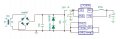
Since the current is so low a simple zener diode voltage-limiter should be fine, like this :-
If you can't source a single 50V zener you can use two other zeners in series, e.g as shown, with a combined voltage of 50V.
I finished putting together all the components. One component I am not sure about is the inductor mentioned in the LTC3639 buck converter. The datasheet mentions to use ferrite pot-cored type which is not available here. Instead, I managed to get the one which looks like as it is shown in the extreme left in this image: http://www.p-wholesale.com/upimg/5/119a1/leaded-power-inductors-698.jpg . Nevertheless; to test the circuit, I connected at the o/p one 3.5 V LED with 100 ohm resistor. The LED lit up only for a few (may be 10 secs) seconds. This was after charging the 10 mF capacitor to 51 V. Noticed the current going way above (twice or thrice) the calculated 15 mA current. I really don't know what is happening here. How do I find the issues with this circuit. Also noted that when there is nothing connected at the o/p, the o/p shows the same voltage as that of the charged capacitor. Is this normal?
If you are asking for inductor datasheet, inductors available here don't come with any datasheets. What we get to see is only the inductance value which is written on the component. Nothing about other parameters.
Looked at the circuit connections again and found a few stray metal pieces stuck between connections which were not supposed to be connected which I think might be the cause of saturation. So, got rid of them quickly and now I notice a completely different behavior. When the cap voltage is 50 V and then discharged through the LED and 82 ohm resistor, the current is limited to around 18 mA which is what I am looking for until the voltage drops to around 34 - 35 V when the current shoots up to 150 mA and stays that way till the cap is completely discharged. When it is again charged to around 30 - 31 V, it exhibits the same behavior when voltage reaches to 26 - 27 V. The similar behavior can be seen at different voltages of charge-discharge cycle. What is this strange behavior?
 Facebook
 Google
 GitHub
 Linkedin