Capacitor bank charging

Thread Starter

vijaykumar1404

Joined Mar 10, 2025
2
Screenshot 2025-03-10 215025.jpg

Hi,
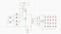
I am trying to build a capacitor charging circuit using a 24V battery. The supercapacitors are connected in series, and the capacitor bank needs to be charged up to 90V
I traced a circuit from a PCB, but I couldn’t complete the tracing as it is a 4-layer PCB, and I need to return it without causing any damage. The MOSFETs used in the circuit are rated at 60V, 75A.
I attempted to design a push-pull topology using 700V MOSFETs, but I encountered excessive drain-to-source voltage spikes, even after implementing a large RC snubber network.
Could someone help complete the circuit and explain its working? That would be extremely helpful.
Thank you!
 

Thread Starter

vijaykumar1404

Joined Mar 10, 2025
2
Oh, it is the two-junction type of MOSFET!

What is the polarity of the spike? Do both transistors have this spike?


The spike issue is in a different circuit that uses a push-pull topology, and yes, both MOSFETs in that topology experience the spike.

However, I want to confirm if the uploaded circuit is correctly traced from the PCB. I am unable to fully understand how it works, and I noticed that no snubber network was used in the PCB. If the circuit is correct, please explain its operation. If not, kindly correct it.

Thank you!
 

Attachments

ronsimpson

Joined Oct 7, 2019
4,645
I have had problems with charging large numbers of capacitors in series. They do not charge up evenly.

I do not understand the capacitors on the left side. (capacitors in series again)
There is a 24V supply (battery) but you are using 1.5kV caps and 700 volt MOSFETs. I think you could use 100V or 50V parts on the left side.
 
Top