 Facebook
 Google
 GitHub
 Linkedin
Hi All,
I have designed a resonant LCC converter for my thesis. It has been some time since I visited the theory and believe I used the following document by Robert Steigerwald to select the resonant components: IEEE Xplore Full-Text PDF:
I was attempting to rearrange this equation for the parallel resonant capacitor, CP, so that I could calculate what value it needs to be at my switching frequency, resonant frequency, Q factor, input/output voltage requirements, and I get the following equation when simplified:
CP = 8.56nF + j22.72nF.
My question relates to the fact that this number involves a complex number. Now, it's been many years since I worked with a complex number, so this is a pretty basic question - but what exactly does this part of the equation relate to? Obviously, the parallel capacitance cannot have any reactive parts, so I placed a capacitor of 9nF into my simulation, and I happily get the 3,000V output voltage from my 243V input, as theory would suggest. I made it slightly larger to account for circuit voltage drops and other inefficiencies. So it seems that it would be appropriate to take only the real part of the above equation into the calculation for the required parallel capacitor - but the "imaginary" part must have some kind of function that possibly "changes" the effective voltage gain - I assume, since this is a variable frequency controller, is demonstrating how the gain changes as the operating switching frequency deviates higher and further away from the series resonant frequency.
So my question is, is it appropriate to ignore the effect of the gain attenuating frequency term when calculating the parallel resonant capacitance? Is there any effect of this gain variation on the selection of the parallel resonant capacitance that I should concern myself with?
I have done a lot of searching today regarding this and haven't came across anything of use. It seems so obvious to just ignore the complex term but I'd like to be able to fully understand its effect on the gain with respect to the capacitance values!
Best regards,
SIC
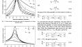
I have attached an image here for those who may not have access to IEEExplore.
I have designed a resonant LCC converter for my thesis. It has been some time since I visited the theory and believe I used the following document by Robert Steigerwald to select the resonant components: IEEE Xplore Full-Text PDF:
I was attempting to rearrange this equation for the parallel resonant capacitor, CP, so that I could calculate what value it needs to be at my switching frequency, resonant frequency, Q factor, input/output voltage requirements, and I get the following equation when simplified:
CP = 8.56nF + j22.72nF.
My question relates to the fact that this number involves a complex number. Now, it's been many years since I worked with a complex number, so this is a pretty basic question - but what exactly does this part of the equation relate to? Obviously, the parallel capacitance cannot have any reactive parts, so I placed a capacitor of 9nF into my simulation, and I happily get the 3,000V output voltage from my 243V input, as theory would suggest. I made it slightly larger to account for circuit voltage drops and other inefficiencies. So it seems that it would be appropriate to take only the real part of the above equation into the calculation for the required parallel capacitor - but the "imaginary" part must have some kind of function that possibly "changes" the effective voltage gain - I assume, since this is a variable frequency controller, is demonstrating how the gain changes as the operating switching frequency deviates higher and further away from the series resonant frequency.
So my question is, is it appropriate to ignore the effect of the gain attenuating frequency term when calculating the parallel resonant capacitance? Is there any effect of this gain variation on the selection of the parallel resonant capacitance that I should concern myself with?
I have done a lot of searching today regarding this and haven't came across anything of use. It seems so obvious to just ignore the complex term but I'd like to be able to fully understand its effect on the gain with respect to the capacitance values!
Best regards,
SIC
I have attached an image here for those who may not have access to IEEExplore.
Attachments
-
 263.5 KB Views: 11


