Can't get staircase timer to work

Thread Starter

cachophrastus

Joined Mar 30, 2019
17
Hi,

I have purchased a Chinese staircase timer. ALC18. (230v AC) Apparently there are several Chinese firms that all make this identical product.

I can't get it to work. I have no electrical knowledge. I'm relying on a freelance so called electronics engineer to show me how to wire it. He is in Sri Lanka. I'm in the UK.

So far he has given me 2 different circuit diagrams but neither of them worked. I want to wire the timer up to just one light to make sure it works and get a feel for how it works.

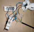
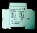
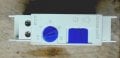
I'm attaching the wiring diagram on the timer, pictures of the timer and a picture of the simple light switch I bought. 4 Contacts on the timer: Top 2 - L an 1. Bottom 2 N and 2. Can someone give me a wiring diagram that will work please?
 

Attachments

Last edited:

LesJones

Joined Jan 8, 2017
4,511
Connect the mains neutral to "N" on the time switch. Connect the mains live to "L" on the time switch. Connect one side of the light (s) to To neutral. Connect the other side of the light (s) to "1" on the time switch. Connect one side of the push button to neutral. connect the other side of the push button to "2" on the time switch. If you are using more than one push button (For example one at the top of the stairs and one at the bottom of the stairs.) just connect them in parallel with the first push button. I did not draw a diagram as it would be just the same as the left hand diagram on the switch except it would not have the switch to override the timed function. (This is the switch labelled "Fix on".)
What is the relevance of the picture of the two way switch ?

Les.
 

Thread Starter

cachophrastus

Joined Mar 30, 2019
17
`HI Les,

I'm still struggling.

1. "Connect the mains neutral to "N" on the time switch".>>> OK.

2. "Connect the mains live to "L" on the time switch" >>>OK.

3. "Connect one side of the light (s) to To neutral " >>> I'm using an electronic ballast to power a fluorescent tube. The ballast has a neutral and live input. So I connect the neutral from the ballast to what? To neutral of the mains? To N of the timer? To 2 of the timer?.

4. "Connect the other side of the light (s) to "1" on the time switch." >>> This would be from the live of the ballast to the timer. Correct?

5. "Connect one side of the push button to neutral." >>> Neutral from the mains?

6. "connect the other side of the push button to "2" on the time switch." >>> So this is a neutral (blue) wire. Correct?

If you are using more than one push button (For example one at the top of the stairs and one at the bottom of the stairs.) just connect them in parallel with the first push button. I did not draw a diagram as it would be just the same as the left hand diagram on the switch except it would not have the switch to override the timed function. (This is the switch labelled "Fix on".)

"What is the relevance of the picture of the two way switch ? " >>>> It's just a switch I bought at a hardware store. I connect one neutral wire to the connector labelled 1 way and another neutral wire to the connecter marked common. Correct?

I have attached the wiring diagram that I have used. When I plug in to the mains with this wiring set up the ballast and the fluorescent tube light up. But then, regardless of whether I switch the external switch on and off or what I do to the timer, the fluorescent tube stays lit up. The timer is not coming on. The timer has a simple clock mechanism inside it right? So if it is working I should hear a ticking sound. Right?
 

Attachments

MrChips

Joined Oct 2, 2009
34,807
If it is a solid-state design (i.e. using computer chips, like your digital wristwatch) there will be no ticking sound).
 

LesJones

Joined Jan 8, 2017
4,511
The way that you have shown in the diagram in post #3 corresponds with the left hand diagram on the time switch in post #1 I noticed today that the left hand diagram pulses the control input (Terminal 2 ) to neutral. The right hand diagram pulses it to live. I don't know if this is an error or if it is designed to work either way. The connections to use on your push switch are the "C" terminal and the one that makes contact with with the "C" terminal when the button is held pressed. I suggest that you start testing using an old fashioned filament lamp as the time switch may use a triac for switching the load rather than a relay. If it does use a triac then it may not work with the fluorescent ballast.

Les.
 

Thread Starter

cachophrastus

Joined Mar 30, 2019
17
Hi Les,

I will try with a filament lamp on Monday. If it works then your theory about the triac would seem to be correct. Supposing it is correct, is there any way that the timer can be adapted to work with a fluorescent ballast?

Cheers Chris
 

Thread Starter

cachophrastus

Joined Mar 30, 2019
17
If it is a solid-state design (i.e. using computer chips, like your digital wristwatch) there will be no ticking sound).
Hi Les,

I tried with a filament lamp. Same thing. When I plug in to the mains the light comes on and stays on.
The way that you have shown in the diagram in post #3 corresponds with the left hand diagram on the time switch in post #1 I noticed today that the left hand diagram pulses the control input (Terminal 2 ) to neutral. The right hand diagram pulses it to live. I don't know if this is an error or if it is designed to work either way. The connections to use on your push switch are the "C" terminal and the one that makes contact with with the "C" terminal when the button is held pressed. I suggest that you start testing using an old fashioned filament lamp as the time switch may use a triac for switching the load rather than a relay. If it does use a triac then it may not work with the fluorescent ballast.

Les.
Hi Les,

I tried with a filament lamp. Same thing. When I plug in the light comes on and stays on regardless of what I do to the timer or the switch. The timer did switch off once. But I'm not sure what combination I did of turning the switch on, turning the timer on or whatever and I could not reproduce it. I think either the timer is faulty (but this is the second one I've bought) or there is something wrong with the way I've wired it up. I'm going to try buying some different makes. It would be good if I can get one from the actual maker and not some Chinese copy.
 

LesJones

Joined Jan 8, 2017
4,511
With the filament connect it up as in post #3 but do not connect anything to terminal 2 on the timer. Set the timer to the minimum time. (I assume that this is half a minute.) Apply power to the circuit an wait for more than 30 second to see if the light goes out. This is working on the theory that it may starts a timing sequence when power is first applied. If the light does not go out then I think the timer is faulty.

Les.
 

Thread Starter

cachophrastus

Joined Mar 30, 2019
17
With the filament connect it up as in post #3 but do not connect anything to terminal 2 on the timer. Set the timer to the minimum time. (I assume that this is half a minute.) Apply power to the circuit an wait for more than 30 second to see if the light goes out. This is working on the theory that it may starts a timing sequence when power is first applied. If the light does not go out then I think the timer is faulty.

Les.
Hi Les,

Yes. That worked. I've attached a photo of the wiring taken before disconnecting to terminal 2.

Edited to add. It worked first time but I can't reproduce it.
 

Attachments

Last edited:
Top