I can't calculate internal resistance of my batteries to match measured

Thread Starter

tsmspace

Joined Mar 16, 2026
35
I recently bought some 18650 analyzers. I have also ordered but not yet received some more "test equipment" styled battery resistance testers (the rc3563 and the frnsi hrm-10).

I watched a video where someone did some calculations against a resistor while reviewing the rc3563, and have tried the same thing, with a similar result. Using a multimeter, I calculate a completely different internal resistance than what I measure. However, the calculated resistance doesn't appear to make sense when compared to discussed appropriate battery resistances, while the measured one makes sense. Here is the video where the rc3653 is compared against some calculations, and with similarly differing results.

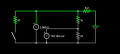
In my case, my xtar vx2 Pro measures 2 of my cheap 18650's taken out of a cheap laser to read around 110 ohms (it also measured them at 200 and 400 mah). I used a similar calculation by measuring the battery voltage then the voltage while shorting a resistor (a 7.5 ohm resistor) where I calculated around 450 ohm. In this test I measured two ways, one of them using a pcb included ampmeter which also verified the resulting amp calc of around 500mA . Here are my measures and results from two separate tests.


open circuit voltage: 4.05

under load 3.8

amps 0.5

.41 R_internal

-----------

Ir = (v1-v2)/(v2/R) *1000

v1 4.03
v2 3.80
R 7.5

Ir 453.947mOhm

There are a number of reviews comparing battery testers to other battery testers, all of which provide results which align with battery ratings and various online suggested "healthy battery resistances", while my calculations show batteries that should be completely dead, while my measurements of my cheapy batteries make sense for the quality and age and performance of them. (they are those ultrafire 5000's, which when new give 1000 to 1500 mah) . Then, the only video showing the calculation as recommended by the internet ai shows roughly the percent difference between calculated and measured than what I get, which is about a 4x difference in both cases. What's going on? How should I do it correctly? I feel like I should not trust measuring equipment unless I can understand it, especially after having so many multimeters fail over time (cheapy ones of course, all kinds of failures but to include accuracy). I want to verify the readings on the xtar vx2pro, or use some other equipment, but everything I can find for instructions on how to calculate results in a massive error value. What am I missing?

Thanks in advance! I am actually wondering if the equipment just works differently, produces a totally different value, but has become standard, as I do not see how anyone is calculating the same values as what is presented for example by the rc3563, or xtar vx2pro.
 

Thread Starter

tsmspace

Joined Mar 16, 2026
35
The xtar vx2 Pro tests at 300mA.
You might try that current to see if you measure a different value with your voltmeter.
it shows its test current, which at the time of my measurements was 500mA although later in the testing it did slowly fall through this 300mA range.

when using the little pcb capacity tester (( HiLetgo Battery Capacity Meter Discharge Tester Analyzer 1.5V-12V Battery Capacity Meter Discharge Tester - Amazon.com )) I was unable to measure current with the multimeter, as the device went to error3 while the multimeter was in the loop. I have not tried measuring with just the resistor through the ampmeter so I suppose I will try this next. Probably this evening, though, so there will be a delay in my response.

thanks!
 

crutschow

Joined Mar 14, 2008
38,316
Better might be to measure the voltage at two different currents (e.g. 100mA and 500mA) and use the voltage and current difference to calculate the resistance.
The open-circuit voltage may not be a good value for one of the voltages to use for the calculation.
 

schmitt trigger

Joined Jul 12, 2010
2,027
As Cruts mentioned the slope between the pair of measurement points would be a far improved measurement strategy.
If the currents between those measurement points fall within the your expected load range, it would be even better.
 

panic mode

Joined Oct 10, 2011
4,864
if your battery measures 4.05V with no load, and 3.80V under load then voltage drop is 4.05-3.80=0.25V.
if that drop is due to load current of 500mA (that is 0.5A) then battery internal resistance is voltage drop divided by load current or in this case 0.25V/0.5A = 0.5 Ohm.

you can try the same using different loads as long as they are rated for your battery.
if your battery tester is any good, results should be pretty close.


don't believe me, do the math yourself. if your load was drawing 0.5A at 3.8V then load resistance is 3.8V/0.5A=7.6Ohm.

but that is just the load itself. when you add battery internal resistance (already determined as 0.5 Ohm) then total resistance in the circuit is
0.5Ohm + 7.6 Ohm = 8.1 Ohm.

and 4.05 V (unloaded voltage) / 8.1 Ohm (total resistance in the circuit) = 0.5A (load current).

the problems you may have when you measure current because burden of your DMM will add some resistance to the circuit and measured current will be slightly lower. so more accurate results would be obtained by using two DMM - one to measure current, the other to measure battery voltage.

the other thing to keep in mind, using power resistor without listed tolerance means the resistance is easily 10% or 20% off. and so will be your results. DMMs cannot directly measure low value resistors accurately. so simply reading value of the resistor will mislead you. that "5 Ohm resistor" could be and likely is something else, possibly 4-6 Ohm.
 
Last edited:

Thread Starter

tsmspace

Joined Mar 16, 2026
35
if your battery measures 4.05V with no load, and 3.80V under load then voltage drop is 4.05-3.80=0.25V.
if that drop is due to load current of 500mA (that is 0.5A) then battery internal resistance is voltage drop divided by load current or in this case 0.25V/0.5A = 0.5 Ohm.

you can try the same using different loads as long as they are rated for your battery.
if your battery tester is any good, results should be pretty close.


don't believe me, do the math yourself. if your load was drawing 0.5A at 3.8V then load resistance is 3.8V/0.5A=7.6Ohm.

but that is just the load itself. when you add battery internal resistance (already determined as 0.5 Ohm) then total resistance in the circuit is
0.5Ohm + 7.6 Ohm = 8.1 Ohm.

and 4.05 V (unloaded voltage) / 8.1 Ohm (total resistance in the circuit) = 0.5A (load current).

the problems you may have when you measure current because burden of your DMM will add some resistance to the circuit and measured current will be slightly lower. so more accurate results would be obtained by using two DMM - one to measure current, the other to measure battery voltage.

the other thing to keep in mind, using power resistor without listed tolerance means the resistance is easily 10% or 20% off. and so will be your results. DMMs cannot directly measure low value resistors accurately. so simply reading value of the resistor will mislead you. that "5 Ohm resistor" could be and likely is something else, possibly 4-6 Ohm.

ok. so , does this mean that the xtar vx2pro , when displaying 100 mOhm as the battery internal resistance, is wrong? Also, in the op, I shared a video link where someone uses the rc3563 and measures very different values than what they calculated using the same math you just walked through. Are these testers all wrong?
 

Thread Starter

tsmspace

Joined Mar 16, 2026
35
Better might be to measure the voltage at two different currents (e.g. 100mA and 500mA) and use the voltage and current difference to calculate the resistance.
The open-circuit voltage may not be a good value for one of the voltages to use for the calculation.
Ok, so I am home again, had some dinner, and really tried to do a test. The test still uses an open circuit voltage, but it checks the voltage while one multimeter is in the circuit as an ampmeter.

Here is the setup: I have two alligator clip wires, a 7.5 Ohm 5watt resistor, one multimeter in amp-meter, one in volts, and a lion in a holder with wires. I clipped the common of the ampmeter to the negative of the battery, I clipped the positive of the ampmeter to the resistor. I stuck the common of the voltmeter into the alligator clip holding the battery negative. I used my hands to hold the positive of the voltmeter to the end of the resistor that will connect to the battery, I measured v1. Then, I used both hands to hold the voltmeter positive, the positive of the battery, and the resistor lead together to measure v2 and A.

v1: 4.04 , v2: 3.83 , A 0.42.

Then I calculated .5 Ohm as the internal resistance. This is consistent enough with all of my other multimeter calculations that I feel they are all about the same, all of my "voltmeter calculations" are in the ballpark of eachother such that I do feel the method is overall correct.

I am awaiting some more battery resistance testers, but the two that I do have both read that battery at about 110 mOhms. These are both lion 18650 + etc. charger/testers ,,, the xtar vx2pro, and the dc2bt charger analyzer. The other variation in the calculations was 450-500 mOhms, not terribly precise but between my junky old multimeter and unpredictable resistance in various harnesses, contacts, etc. in the various configurations I feel that 50 mOhms isn't enough to jump on a problem (at my experience level), ,, however when there are TWO separate consistencies that differ significantly (by 400%) and can be sorted by "calculated vs. tested" , I feel there is reason to consider there is something that is either not working, or that I don't know!!

and of course my result compares to the result in the linked video, using a "higher quality looking" tester with results that would probably compare to my 18650 chargers results. And this is the only video I can find where someone measures a battery, then calculates it immediately afterwards in order to try and validate the measurement.
 

vandveuser16776

Joined Feb 21, 2026
121
This is how I would do the test. Since putting the battery under a heavy load will naturally drain the battery, no matter how much, testing it under a load does not give you the internal resistance. That would be correct if the battery's capacity was infinite, but it is not. The DIY method needs two voltmeters. Unfortunately, voltmeters do not show 10 digit decimal so you need to make a voltage divider, so you can measure mV or even uV with regular, cheap multimeters. Then press the switch, read both multimeters and read the one that is directly connected to your battery, to see if the voltage has dropped below the initial value before you started the test. Then repeat this process several times and get the average of all your readings, then put it in the Ohm's law. For the same reason the I mentioned, I added a resistor (that 8.2Ω) to simulate some real world scenario, as the simulators have no internal resistance for power supplies. You can simulate it on Falstad
 

Attachments

Sensacell

Joined Jun 19, 2012
3,767
How you take these measurements has a huge impact- contact resistance!
You want to use the "4-terminal" technique to eliminate battery contact resistance as much as possible.
 

crutschow

Joined Mar 14, 2008
38,316
I am home again, had some dinner, and really tried to do a test. The test still uses an open circuit voltage,
You quoted my post about using two different loads, but then still used the no-load open circuit voltage.
Why not try two different loads, and the voltages and currents at those two loads to calculate the resistance as I suggested?
 
Last edited:

drjohsmith

Joined Dec 13, 2021
1,548
The way we teach and why,
batteries internal resistance is not constant, varies over temprature , charge level, current taken
batteries such as Li have battery circuits inside that are none linear
The effect of the external circuit , due to the low resistance numberes is critical, you can not change a meter around to measure volts then amps. you need to measure both v and i zt the same time.

so.

two meteres , and a variable load.
one meter for voltage direct as possible across the battery , one for current through the load.

make a sucession of meassurments over different currents, plot the graph.

the slope gives you the value!
and also gives you idea as to the reality.
 

gaber2611

Joined Mar 14, 2013
321
What the case if battery you measuring internal resistance?, fully charged?, or empty?, in rest or no?
I work on lead acid battaries for UPS machines, I use this tester or 12v automotive lamp with multimeter " voltage drop check on battery" Screenshot_20260317_203956_com_amazon_mShop_android_shopping_MainActivity.jpgwhen I've charged the battaries, and them test with the tester, all gave good result, and after like 30 mins or 1 HR or next day test, some which was good result gave replace result
That confused me alot like you
But after some search, I've figured out to test the battery it should be at rest, not in charging cycle at all for sometime for better result, or accurate result

What type of battery you test?, how much voltage ocv?
 

Attachments

Thread Starter

tsmspace

Joined Mar 16, 2026
35
Does anyone know of a video where a resistance tester is used, AND a calculation experiment is performed in the same video to prove a similar result?
 

Thread Starter

tsmspace

Joined Mar 16, 2026
35
You quoted my post about using two different loads, but then still used the no-load open circuit voltage.
Why not try two different loads, and the voltages and currents at those two loads to calculate the resistance as I suggested?
I tried: a closed circuit with a 7.5 Ohm load, then I added in parallel another 7.5 Ohm load (meaning it switches to a 3.75 Ohm load). I measured:

v1: 3.05 , v2: 2.47, a1: 0.39, a2: 0.64

I am not sure the correct way to apply these numbers, but assuming the "slope" suggesting of v1-v2/a1-a2 I get: -2.32Ohms. So, considering the negative number, I am curious about this result, as Ohms is not really a "negative number" kind of thing. If I use only a2 I get 906 mOhms , if I use only a1 I get 1.48 Ohms, and if I measure with my shiny new rc3563 I get about 110 mOhms, which aligns with my other test equipment that displays "battery resistance" somehow.

I guess I can imagine that my alligator clips and all the associated wires and test leads, there is extra resistance, but I'm not sure how I should go about a negative ohms, and then I don't know if there should be 1 whole ohm, if this is nothing or huge, or what. given the original calculation, I would be at around .5 ohms vs. .1 ohms, so then basically for that test all leads, clips, wiring, battery holder contacts, etc. we are talking about .4 ohms. I suppose I can imagine this is small enough to come from all of this cheapy stuff. (It's not like I'm using gold plated pure wires etc. it's all just cheapy stuff) . But I have no way to visualize just how much all of this should impact my result. It's all "first time" kind of stuff.
 

drjohsmith

Joined Dec 13, 2021
1,548
I tried: a closed circuit with a 7.5 Ohm load, then I added in parallel another 7.5 Ohm load (meaning it switches to a 3.75 Ohm load). I measured:

v1: 3.05 , v2: 2.47, a1: 0.39, a2: 0.64

I am not sure the correct way to apply these numbers, but assuming the "slope" suggesting of v1-v2/a1-a2 I get: -2.32Ohms. So, considering the negative number, I am curious about this result, as Ohms is not really a "negative number" kind of thing. If I use only a2 I get 906 mOhms , if I use only a1 I get 1.48 Ohms, and if I measure with my shiny new rc3563 I get about 110 mOhms, which aligns with my other test equipment that displays "battery resistance" somehow.

I guess I can imagine that my alligator clips and all the associated wires and test leads, there is extra resistance, but I'm not sure how I should go about a negative ohms, and then I don't know if there should be 1 whole ohm, if this is nothing or huge, or what. given the original calculation, I would be at around .5 ohms vs. .1 ohms, so then basically for that test all leads, clips, wiring, battery holder contacts, etc. we are talking about .4 ohms. I suppose I can imagine this is small enough to come from all of this cheapy stuff. (It's not like I'm using gold plated pure wires etc. it's all just cheapy stuff) . But I have no way to visualize just how much all of this should impact my result. It's all "first time" kind of stuff.
two points ?
to use a graph you need 5 plus point.
are you meassuring the current and across the battery at the same time?
the point of meassuring at same time is the exteral resistance has no effect on the messurments accuracy, itscwhats called a 4 terminal or kelvin messurment,
can you share picture of your set up please, showing the battery, two meteres , wires and load.

negative resistance ? Id pattent it if you think its real, alternatively, you have the current or voltage direction wrong ..
 

Thread Starter

tsmspace

Joined Mar 16, 2026
35
two points ?
to use a graph you need 5 plus point.
are you meassuring the current and across the battery at the same time?
the point of meassuring at same time is the exteral resistance has no effect on the messurments accuracy, itscwhats called a 4 terminal or kelvin messurment,
can you share picture of your set up please, showing the battery, two meteres , wires and load.

negative resistance ? Id pattent it if you think its real, alternatively, you have the current or voltage direction wrong ..
I'm not making a graph. The internal resistance formula is for one value for each variable, not for a graph. I'm not working with a nice open space where I can take a nice picture, sorry.
 
Top