Facebook
 Google
 GitHub
 Linkedin
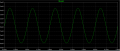
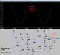
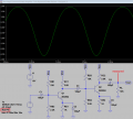
All of a sudden I can no longer run a Transient Analysis on this Two-Stage Amplifier
even though it ran okay before. I am interested in graphing Vout. I didn't knowingly change anything since the other day. Could someone please tell me what I have done to mess it up?
Thanks
even though it ran okay before. I am interested in graphing Vout. I didn't knowingly change anything since the other day. Could someone please tell me what I have done to mess it up?
Thanks
Attachments
-
3.1 KB Views: 21