Basically, it consists of testing the 8 states and determining which one is consistent; besides that, find the current and voltage of the anodes and cathodes.
Well, I'm doing it using the mesh method. However, I'm not entirely sure if I should use that method or another one similar. But I'm not sure if that's right and I want to confirm if I'm doing it right
well, you still did not do the first step.
i do not speak that language and do not know what is asked. aren't there similar forums in that language?
i guess it mentions DC steady state and conditions for diodes to bein on/off state.
if asking for steady state, circuit can be simplified. and then i would solve for voltages at each node with respect to reference (GND).
View attachment 363864
Basically, it consists of testing the 8 states and determining which one is consistent; besides that, find the current and voltage of the anodes and cathodes.
This is interesting because I like to suggest a method like this when dealing with multiple diodes.
We have a possible 8 states for the three diodes (2^N with N=3) so we look at all 8 possibilities.
This circuit can get a little more complicated when we consider the dynamic operation, but luckily here it looks like they are asking for only the DC steady state solution(s). That makes it a lot simpler. That means you can assume the state for the inductors pretty easy. If this allowed time solutions it would be harder to do because we'd have to consider the way the voltage can change.
I do not see any mention of forward voltage, so I guess we can assume the diodes drop 0v when 'on' and completely open when 'off' ?
Worst case is that you have to analyze eight slightly different circuits. But it's always worth taking a step back first and asking if you can deduce the states of at least one of the diodes by inspection and reasoning. Doing so for just one of them cuts the number of circuits in half.
As has already been pointed out, the circuit, since it is DC, can be significantly simplified before you even start. What do capacitors and inductors each look like at DC?
In this case, you should be able to determine the state of all three diodes pretty easily by inspection. Knowing that this is possible may give you the needed encouragement to figure out how to do it.
Once you have determine that, assuming you do so correctly, the voltages at every not should become obvious by inspection and then the currents also become trivial to determine even without a calculator or pen/paper (assuming your are using a diode forward drop of zero volts). Again, knowing that this is the case might be enough to let you decide to put in the effort to see if you can figure it out.
As a check, the only calculations you end up needing to perform is dividing an even number by two and multiplying that same even number by two (well, technically you also need to divide a number by one, but I don't really consider that doing a calculation).
Well, I'm doing it using the mesh method. However, I'm not entirely sure if I should use that method or another one similar. But I'm not sure if that's right and I want to confirm if I'm doing it right
the way i see it you are not doing it right. you did not mark the circuit so nobody can check if your equations make sense. and i am really not in the mood to reverse engineer what someone else was thinking when it is your job to mark things. for example what is to stop me from assuming that currents are something like this:
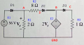
in steady state capacitors are open circuit and inductors are short circuit. then problem reduces to this:
then we mark the currents,... while this is arbitrary, i will use directions that match diode orientation:
assumptions:
Vf_d1 = Vf_d2=Vf_d3=0 ; ideal diodes
A: E1=Vf_d1+Vx
since Vf_d1=0, Vx>=E1 and most definitely Vx>0
B: Vx=I2*R2 + Vf_d2 + 2Vx
Vx=-I2*R2 ; Since Vx>0 (derived from A) amd I2 matches diode direction this is not possible so I2=0 (D2 is off).
Since D2 is off, I2 has no contribution/effect on voltage at node A. the only current through R1 is I1. and from A we see that Vx=E1=56V so I1=Vx/R1=56V/2Ohm=28A and D1 is always on.
C: Since 2Vx=112V>0 and D3 is always forward biased, I3=2Vx/R3
I3=112A
so case C is the only one correct but... if you want to analyse all 8 cases, all you need to do is replace diode with short circuit if diode is on, or open circuit if diode is off. it becomes manial but - it is a good exercise.
so case A (all diodes on), would look like this:
and case B (only D3 is off) would look like this:
etc.
in steady state capacitors are open circuit and inductors are short circuit. then problem reduces to this: View attachment 363945
then we mark the currents,... while this is arbitrary, i will use directions that match diode orientation: View attachment 363946
assumptions:
Vf_d1 = Vf_d2=Vf_d3=0 ; ideal diodes
A: E1=Vf_d1+Vx
since Vf_d1=0, Vx>=E1 and most definitely Vx>0
B: Vx=I2*R2 + Vf_d2 + 2Vx
Vx=-I2*R2 ; Since Vx>0 (derived from A) amd I2 matches diode direction this is not possible so I2=0 (D2 is off).
Since D2 is off, I2 has no contribution/effect on voltage at node A. the only current through R1 is I1. and from A we see that Vx=E1=56V so I1=Vx/R1=56V/2Ohm=28A and D1 is always on.
C: Since 2Vx=112V>0 and D3 is always forward biased, I3=2Vx/R3
I3=112A
so case C is the only one correct but... if you want to analyse all 8 cases, all you need to do is replace diode with short circuit if diode is on, or open circuit if diode is off. it becomes manial but - it is a good exercise.
Just taking a quick look, for your first drawing I think I would include a node for the D2 cathode as well as the others.
This would allow us to calculate the voltage there and compare with B.
Possibly combine this with a diode test voltage drop of maybe 0.001v if these diodes are ideal in the sense that they have no voltage drop when 'on'.
This way if the voltage at the anode is +2.001v and at the cathode it is +2.000v we can assume it is in the 'on' state. On the other hand, if the voltage on the anode is +2.001v and on the cathode it is +2.001v then it is in the 'off' state.
This should work well with Nodal analysis. There will of course be other ways to do it too.
I was going to calculate the node responses for each node in this diode circuit just for the fun of it and as an illustration of how diode circuits can work with the transient response. I looked at the nodes for another five seconds and realized that this circuit question is INCREDIBLY simple to answer. I almost could not believe it. At first glance I figured this was a regular circuit with three diodes and that made it a bit more complicated to solve the transient solutions for each node or at least the output, and maybe given some actual fixed values for all the components. It actually seems to not only be a bit simpler, it's a LOT simpler than we might expect at first glance.
The key is to do what I did naturally. I started to look at how the nodes voltages might behave. Do that and I think you'll see the same thing I saw.
I almost hate to admit I did not see this when I first looked at the circuit. It looked like your typical circuit where everything mattered when you do a transient response calculation. It's nothing like that
Ok so the transient response may be a little tiny bit more involved, but the DC response is way too simple. I almost couldn't believe it.
Hint below ... click to view.
The mere fact that no component values are given for either the inductor or the capacitor should have been screaming out that they have no effect on the results.
Ask yourself, is it possible Diode D1 is off? it has 56V screaming into it's anode and if it is OFF there is no Vx, thus guaranteeing no voltage at its cathode. Then with it on, ask the same question about D3...when you realize they MUST both be on, then deal with D2. When you realize how big 2Vx is at D2's cathode and then realize you can't match it on the other end, you see its off. Then circuit analysis becomes pretty easy with the resulting circuit.
Ask yourself, is it possible Diode D1 is off? it has 56V screaming into it's anode and if it is OFF there is no Vx, thus guaranteeing no voltage at its cathode. Then with it on, ask the same question about D3...when you realize they MUST both be on, then deal with D2. When you realize how big 2Vx is at D2's cathode and then realize you can't match it on the other end, you see its off. Then circuit analysis becomes pretty easy with the resulting circuit.
One subtle point that is easy to overlook, which you may or may not have considered, is the case when the independent source's output is negative. The first part of your analysis still holds, which leads to an easy solution for this particular circuit, but in the more general case, it's easy to conclude that since the voltage to the left of D2 (to the left of the 8 Ω resistor, specifically) is Vx and that to the right of D2 it is 2Vx, that that means that the voltage to the right is always higher than the voltage to the left and get led astray if the circuit is designed such that Vx turns out to be negative.
Yes - spot on! Using D2 with the 2Vx and Vx is also intuitive. If Vx would've been negative (could not really be in this case with the way circuit is drawn) you would have to think the other way around wrt the diodes.
One subtle point that is easy to overlook, which you may or may not have considered, is the case when the independent source's output is negative. The first part of your analysis still holds, which leads to an easy solution for this particular circuit, but in the more general case, it's easy to conclude that since the voltage to the left of D2 (to the left of the 8 Ω resistor, specifically) is Vx and that to the right of D2 it is 2Vx, that that means that the voltage to the right is always higher than the voltage to the left and get led astray if the circuit is designed such that Vx turns out to be negative.
Yes I agree. If either Vx is flipped or 2*Vx is flipped, we see the opposite state for D2.
That's a different circuit though, but it is true that changing the states of some of the elements leads to other interesting circuits too.
So for the ideal zero voltage drop diodes the key always lies in the difference between VA and VB in the diagram.
 Facebook
 Google
 GitHub
 Linkedin


")