Can Someone Help Me with This paltry 555 Timer Related Dilemma?

Thread Starter

BenGrimaldi

Joined May 28, 2025
11
Synopsis: I am trying to create a timer circuit that when triggered, will result in a water pump activating and pumping water for 11 seconds.

Figure 1 is the timer circuit connected to a piezo buzzer as my test load and it works flawlessly, a touch of the pushbutton switch causes the piezo to sound for exactly 11 seconds. If I measure the voltage on pin 6 of the 555, I see it charge up to 4V (which is 2/3 of 6.06) in 11 seconds then discharge.

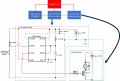
I put the pump into my load circuit (The centerpiece is a cheap waterpump rated at 2.5 – 6.5 VDC 1.28 W) that replaces the piezo, as shown in Figure 2 and it no longer works. When I press the momentary pushbutton switch will not turn on the pump, but if I hold the button in, the pump will run as long as the button remains held. I monitored pin 6 of the 555 Timer and saw that the capacitor CT will only charge up to about 1.45V and stay there if I hold the button in!

This is repeatable as I switch between my unit-test load (piezo buzzer) and load circuit (BJT driven water pump).

Things I tried:
  • I replaced my timing components to be RT = 1MΩ and CT=10μF to rule out a high capacitance drawing too much current and I get the same results.
  • I replaced the load circuit with an N-channel MOSFET solution and got the same results.
  • As much as I dislike blind shotgunning - replaced 555 and still fails

I would appreciate any ideas on other things I can try or what I may be missing. I have tons of test data so any other questions needed for clarification, let me know as well. Thanks in advance!
 

Attachments

Alec_t

Joined Sep 17, 2013
15,101
Welcome to AAC!
Possible causes:
1) The pump rating implies a running current of about 200mA, but start-up current will be many times that, e.g. about 1A or even more. Can your power supply provide that much current? The fact that the cap only charges to 1.45V suggests it can't.
2) The transistor needs to be turned fully on if it is not to drop too much voltage. So its required base current might be as high as ~100mA at start-up. You can't get that much current with a 987Ω base resistor and a 6V supply.
 

schmitt trigger

Joined Jul 12, 2010
2,027
Since you already checked with a Mosfet instead of a bipolar transistor, my best guess would be similar to Alec’s suggestion #1.
The inrush current may be too large.
 

Thread Starter

BenGrimaldi

Joined May 28, 2025
11
Welcome to AAC!
Possible causes:
1) The pump rating implies a running current of about 200mA, but start-up current will be many times that, e.g. about 1A or even more. Can your power supply provide that much current? The fact that the cap only charges to 1.45V suggests it can't.
2) The transistor needs to be turned fully on if it is not to drop too much voltage. So its required base current might be as high as ~100mA at start-up. You can't get that much current with a 987Ω base resistor and a 6V supply.
Hmmm....the water pump directly connected to the PS runs fine at values from 2V to 6V (112mA - 300 mA) but I can see with a transistor switching and a coil, the startup current could be interesting. I may try some different (lower) base resistors to increase base current to see if that changes anything - will certainly let you know!!! I appreciate the suggestions!
 

Thread Starter

BenGrimaldi

Joined May 28, 2025
11
Since you already checked with a Mosfet instead of a bipolar transistor, my best guess would be similar to Alec’s suggestion #1.
The inrush current may be too large.
Thank you for taking time to help me! As I mentioned to Alec, the water pump directly connected to the PS runs fine at values from 2V to 6V (112mA - 300 mA) but I will try some different (lower) base resistors to increase base current to see if that changes behavior.
 

MisterBill2

Joined Jan 23, 2018
27,159
Certainly the previous posts are correct! So I suggest trying it with a totally separate power source for the pump motor. Then let us know what happens.
 

Thread Starter

BenGrimaldi

Joined May 28, 2025
11
Certainly the previous posts are correct! So I suggest trying it with a totally separate power source for the pump motor. Then let us know what happens.
Yes - I am arriving at that same conclusion as something to try. I will try that and report back to everyone with details and data. I appreciate everyone's help regardless! Stay tuned...
 

MisterBill2

Joined Jan 23, 2018
27,159
Resistance connection issue between what components were you thinking?
Resistance in the wiring between the power source and the motor that is shared with the timer circuit. But that might include internal resistance of the power source, which is why I suggested trying a separate motor power supply. Sorry I was not clear enough.
 

Thread Starter

BenGrimaldi

Joined May 28, 2025
11
OK everyone - separating the power sources made the circuit work deterministically, though not EXACTLY as designed. In general, my 555 output would now reliably create a voltage drop of 3.32 V across the base resistor (resulting in a base current of 3.36 mA) and with Vb = 1.16V, Vc = .6V and Ve grounded, I have Vb>Vc and Vb>Ve so my BJT is in saturation. Now the only bugaboo was my 11 second "pump on" time seemed to be closer to 6 seconds. So, I changed my timing resistor from 1Mohm to 2Mohm to bump it up and I was getting closer to 15-20 seconds which is fine for this hobby-level application.

I appreciate everyone's help!!

So, from my high level design (figure attached) I am getting closer...just need a clock circuit to provide a pulse to turn the pump on at particular time intervals (every X hours) and a power distribution scheme (was hoping to share a power source but that prevented deterministic operation). Will certainly keep everyone posted!
 

Attachments

Top