 Facebook
 Google
 GitHub
 Linkedin
Hello everyone,
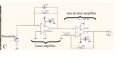
I'm working on a project with a sensor which has an analog circuit to convert output current signal of photodiode to voltage like attached in the file. I'm not so specialized in analog circuit but I really want to understand how this circuit can convert from current to voltage. Can you explain in detail how does it work (the sub-component linear amplifier and non-inverter amplifier)?
Here is the only information written in the report about this circuit but I can't understand well:
- The linear amplifier part is an analog low-pass filter with a cutoff frequency equal to 106kHz. Considering the high gain given by the resistance of 150kOhm, the linear amplifier aims at preventing signal from oscillations.
Thank you for your explanation.
P/S I also attach the paper of the sensor.
Attachments
-
 41 KB Views: 25
 -
4.2 MB Views: 10


