hello everyone,
I want to create a radio transmitter circuit and understand how it works but cannot find the role of resistor 330R and capacitor 4p7 in the schematic.
thanks in advance.
The transistor operates as a common-base amplifier for the RF. Its RF input is at the emitter that cannot be shorted to ground.
The 4.7pF capacitor provides positive RF feedback from the collector to the emitter so that it oscillates.
Its simplicity causes problems;
Since the capacitance of the transistor changes as the battery voltage runs down then the RF frequency will also change.
Since the tuned circuit is at the antenna then the RF frequency will also change if something moves towards or away from the antenna.
Since the output level from the microphone is very low it needs a mic preamp or the received sound produced from an FM radio will also be very low.
Since all FM radio stations produce pre-emphasis (treble boost) and all FM radios produce matching de-emphasis (treble cut) then the received sounds will be muffled with high frequency sounds reduced.
Everybody who complained that this circuit does not work built it with a messy tangle of long wires on a breadboard. They did not know that each wire has inductance and capacitance to other wires and the rows of contacts on the breadboard also have inductance and capacitance between them and to the wires.
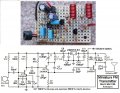
I built mine compactly soldered on a stripboard with all the problems I mentioned fixed, and it works perfectly:
Hello there Echoing my superiors.
The 4p7 capacitor across the transistor serves to keep the tank circuit vibrating. In theory, as long as there is a supply voltage across the parallel inductor and variable capacitor, it should vibrate at the resonant frequency indefinitely. In reality however, the frequency decays due to heating losses. 4p7 is used to prevent decay.
 Facebook
 Google
 GitHub
 Linkedin

")


