Facebook
 Google
 GitHub
 Linkedin

Sounds similar to the one Taryl has:
That's the video that got me started down this rabbit hole in the first place. By the way, when Taryl keeps saying "fixes dead spark plugs", I think he really means "cleans fouled spark plugs"
I have an old reading lamp that used to be dimmable, but the dimming function stopped working 20+ years ago. Not long ago, I decided to give it an LED upgrade. Taking the original dimmer guts out, I saw a similar device as in that thread Ron shared. I didn't understand how it worked, so I set it aside somewhere. Maybe I'll have a closer look at it someday.
So the time interval is important after all. Makes sense. It must work across a range of firing frequencies though, as engines might run from 800 to 5000+ RPM, right? As the engine revs up the spark gets weaker? Would it be the time the switch is closed that is important, or both open and closed?
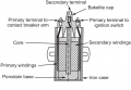
I started looking at voltage boosters, and quickly found an article from this vary website: Understanding the Operation of a Boost Converter. Right away I saw the similarities to the ignition coil circuit, but I'm also seeing differences.
If I'm understanding right, the larger the inductor, the longer it takes to create the full sized magnetic field, but don't let it go too long, or it will saturate, and bad things will happen. Also, the larger the capacitor, (capacitance wise) the longer it will take to fully charge from the inductor when the circuit is opened. A larger capacitor will be able to store more charge, so the size of the capacitor should be related to the size of the inductor.
The values I know so far are the input voltage (12V), the secondary coil winding output voltage (5kV), the permeability of the iron core (0.0063 H/m). I can measure inductance for a known number of turns, and calculate permeance for the inductor (including the air gap) and I can calculate how many turns I'll need for a desired inductance for the primary coil. (And therefore, the secondary too, I guess.)
I still need to figure out what inductance I want for each coil, the capacitor's voltage and capacitance, and how much time is needed to saturate the inductor's magnetic field and how much time is needed to fill up the capacitor with charge.
I came across some equations that might be related to this:
V=Q/C Voltage equal stored charge divided by capacitance.
C=I*D/f*ΔV Capacitance equal current times duty cycle divided by frequency times voltage ripple.
D=Vin/Vout Duty cycle equal voltage in divided by voltage out.
I'm not sure if any of these apply to what I'm doing yet.
That's the video that got me started down this rabbit hole in the first place. By the way, when Taryl keeps saying "fixes dead spark plugs", I think he really means "cleans fouled spark plugs"
I have an old reading lamp that used to be dimmable, but the dimming function stopped working 20+ years ago. Not long ago, I decided to give it an LED upgrade. Taking the original dimmer guts out, I saw a similar device as in that thread Ron shared. I didn't understand how it worked, so I set it aside somewhere. Maybe I'll have a closer look at it someday.
So the time interval is important after all. Makes sense. It must work across a range of firing frequencies though, as engines might run from 800 to 5000+ RPM, right? As the engine revs up the spark gets weaker? Would it be the time the switch is closed that is important, or both open and closed?
I started looking at voltage boosters, and quickly found an article from this vary website: Understanding the Operation of a Boost Converter. Right away I saw the similarities to the ignition coil circuit, but I'm also seeing differences.
If I'm understanding right, the larger the inductor, the longer it takes to create the full sized magnetic field, but don't let it go too long, or it will saturate, and bad things will happen. Also, the larger the capacitor, (capacitance wise) the longer it will take to fully charge from the inductor when the circuit is opened. A larger capacitor will be able to store more charge, so the size of the capacitor should be related to the size of the inductor.
The values I know so far are the input voltage (12V), the secondary coil winding output voltage (5kV), the permeability of the iron core (0.0063 H/m). I can measure inductance for a known number of turns, and calculate permeance for the inductor (including the air gap) and I can calculate how many turns I'll need for a desired inductance for the primary coil. (And therefore, the secondary too, I guess.)
I still need to figure out what inductance I want for each coil, the capacitor's voltage and capacitance, and how much time is needed to saturate the inductor's magnetic field and how much time is needed to fill up the capacitor with charge.
I came across some equations that might be related to this:
V=Q/C Voltage equal stored charge divided by capacitance.
C=I*D/f*ΔV Capacitance equal current times duty cycle divided by frequency times voltage ripple.
D=Vin/Vout Duty cycle equal voltage in divided by voltage out.
I'm not sure if any of these apply to what I'm doing yet.