Building my own spark plug tester. (And understanding ignition coils.)

MisterBill2

Joined Jan 23, 2018
28,029
Yes, thanks for stating that, I wonder what exactly can be measured that lets us detect a difference between a working and a failed or failing, spark plug.

I'd imagine knowing the voltage that is necessary to make it spark would be helpful as well as any leakage/resistance as that voltage rises.
My experience with misfiring spark plugs has been mostly that they present a lower resistance so that there is not enough voltage developed to produce an adequate spark. So my first spark plug check is done with an OHM METER, without even removing the plug from the engine. A simple and easy test.
 

LowQCab

Joined Nov 6, 2012
5,101
Consider that dragster engines still use distributors, though. Evidently performance is more important than cost reduction for some applications.
.
Top-Fuel-Rail-Dragsters and Funny-Cars use 2 Custom-made-Magnetos,
( vaguely similar to the Magnetos used in Piston-Powered-Airplanes ),
with 2-Spark-Plugs per Cylinder, ( also similar to Airplanes ).

These Engines run on Nitro-Methane,
and a misfire can, and usually does, cause a catastrophic-Engine-EXPLOSION.
Obviously they can't afford to have a misfire under full power.

16 Spark-Plugs and 16-new-Valve-Springs, and all Crank/Rod-Bearing-Shells,
are installed for every single run down the Track.
The Spark-Plugs are all completely destroyed, some of them, even before the end of the run.

These Engines are not even remotely similar to an Automotive-Engine
except that they have 8-Cylinders in a "V" shape.
.
.
.
 
Last edited:

LowQCab

Joined Nov 6, 2012
5,101
My experience with misfiring spark plugs has been mostly that they present
a lower resistance so that there is not enough voltage developed to produce an adequate spark.
.
A "Fouled" Spark-Plug acts similar to placing a large Resistor across the Gap.

This causes the Stored-Energy in the Coil to become depleted before
the Voltage gets high enough to jump the Gap.
.
.
.
 

Thread Starter

rebelrider.mike

Joined Feb 2, 2024
53
It seems I've made an inductor! The LCR meter showed up in the mail today, and I got the core wound with 70 turns of wire. The meter showed 89μH, and 0.2Ω. The resistance I can double check with my regular multimeter and it agrees. My little component tester was way off at 0.9Ω. I can also check the resistance with some math. When I put 2V through the coil, my power supply read 7.9A. Ohm's Law says that means the resistance should be about 0.25Ω. That was also enough power to pick up a large steel bolt. And it immediately dropped when I cut the power. It's like being in physics class again, but this time it's fun because I actually want to be here!

Another bit of fun came in the mail today:
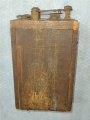
20250522_205931.jpgSo of course I had to use my new LCR meter on it too. I checked the capacitance between the open points and got 84nF. Originally it would have been 400nF from what I've read. But then this appears to be in original condition, so the capacitor would be something like 100 years old.

I have a 470nF "Orange Drop" capacitor coming in the mail next week, so I'll be able to compare the value of a known capacitor with what readings I get on the LCR meter and the component tester. We'll see if they agree at all.
 

Thread Starter

rebelrider.mike

Joined Feb 2, 2024
53
The capacitor came early, and both the LCR meter and the component tester agree on the 470nF capacitor being about 480nF. I did read the manual that came with the LCR meter and it said the smallest settings for both capacitance and inductance may read incorrectly if there is outside RF interference. So I shall disregard those readings and try to avoid them in the future.

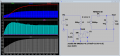
I've made my first attempt at a flyback boost converter in LTspice:FlybackBoostConverter.png It looks like the ones I've seen on the internet I guess. I was surprised at how much current is going through the switch. I suppose that's part of why flyback boosters in real life have lots more components than this simple one. Well, also, I don't know if I designed it right.

I also noticed that when the output capacitor is removed, the output voltage alternates between 0V and around 150V. For the ignition system you'd want that spike in order to jump the gap. And the diode on the output wouldn't be needed because in between sparks the spark plug is sort of doing the diode's job, right?

So back to my home made inductor, with 70 turns and 89μH, I did some math. With 70 squared divided by 0.000089H, I got a reluctance of 55,056,180 H^-1. Then 0.000000018H for permeance, or 0.018μH. Before I move on with other math, does this seem right? I have no idea if these numbers are reasonable.

I don't know if it's necessary, but I had a couple of thoughts to get rid of the air gap in the core. I have a second rod, and could connect the two with a couple of bits of metal, forming a rectangle. The short bits would be regular steel, but at east it wouldn't be air, right? Another idea is to use an old power transformer core instead. I have a couple of those, though there is the new constraint that the coils have to fit physically in the core's cavities. If the original wire is still intact and the right gauge, I'd also have a bunch of enameled wire I could use.
 

Attachments

Top