Because I am utilizing the stock headlight controls. Here's an image of what they look like:
All controls are push buttons that provide a momentary ground to the solid state. When car is turned off headlights de-energize, but headlights can be turned on when car is not running. Even if the key is in the off position.
Headlights On (Square button above button with "P") : Sends momentary ground to solid to state. Low Beams are defualt
Off (Marked "Off"): Sends Momentary ground to solid state. Turns off headlights completely
High Beams (More rectangular button at the top): Provides momentary ground for solid state. If Headlights are not energized pressing the button momentarily activates high beams until button is depressed. If the Headlights are already activated, pressing the button energizes the highbeams. Pressing again de-energizes highbeams.
Do you mean: "pressing the button momentarily activates high beams until button is released"?
The switch could very well be a conductive elastomer. i.e. Like the KB of many remote controls. A rubber-like contact that bridges gold plated traces on the PCB.
That was a great explanation. My design would have some missing features like flash and off when the car turns off.
Do you mean: "pressing the button momentarily activates high beams until button is released"?
The switch could very well be a conductive elastomer. i.e. Like the KB of many remote controls. A rubber-like contact that bridges gold plated traces on the PCB.
Other notes:
a) Power and ground to the IC's don't seem to be shown on the schematic. A lot of times they are noted elsewhere.
b) There are multiple sections in the parts. I didn't see a U5. It might be called U2e in a real schematic. e.g. U2a through U2f for a hex inverter. When you layout, you re-assign to convenient sections.
c) Any unused inputs for these sorts of IC parts need to tied to ground or the supply or they tend to oscillate and die. The selection is usually done by convenience or in your case, the lowest quiescent power which is probably ground.
d) Bypass capacitors are usually ceramic and are located as close to the IC power pins as possible.
Hi
Here is new version but should be the final one.
1. I changed the driver transistors to mosfets.
2. Fixed the ON FF so it latches until the OFF button is pressed.
3. All caps 25v min, Resistors 1/2w,5%, IC's, mosfets, should be Hi temp version if possible.
4. Parts can be SMD but thru hole might be easier.
Other notes:
a) Power and ground to the IC's don't seem to be shown on the schematic. A lot of times they are noted elsewhere.
b) There are multiple sections in the parts. I didn't see a U5. It might be called U2e in a real schematic. e.g. U2a through U2f for a hex inverter. When you layout, you re-assign to convenient sections.
c) Any unused inputs for these sorts of IC parts need to tied to ground or the supply or they tend to oscillate and die. The selection is usually done by convenience or in your case, the lowest quiescent power which is probably ground.
d) Bypass capacitors are usually ceramic and are located as close to the IC power pins as possible.[/QUOTE
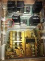
Have you checked that this circuit breaker might just be faulty causing the lights to flash on/off. Ive seen this fault in plenty of cars.View attachment 141247
Have you checked that this circuit breaker might just be faulty causing the lights to flash on/off. Ive seen this fault in plenty of cars.View attachment 141247
Here's an image of the board itself. The circuit breaker is circled in red. When I try to run the headlights it gets VERY hot and the headlight relay begins to click to the open and closed position repeatedly.
I would love to fix the board but I don't know even know where to begin to diagnose the issue. My plan is to build the circuit that eetech posted to bypass the headlight controls, and in the meanwhile try to figure out the issue on the board. It seems as long as the headlight relays are left out everything else works fine.
1. I changed the driver transistors to mosfets.
2. Fixed the ON FF so it latches until the OFF button is pressed.
3. All caps 25v min, Resistors 1/2w,5%, IC's, mosfets, should be Hi temp version if possible.
4. Parts can be SMD but thru hole might be easier.
That circuit breaker should not be getting Hot. There is either too mutch current draw ( headlight globes been changed to higher wattage) or the actual CB is faulty or poor soldering. If you look at the circuit that CB feeds power to the relay solenoids as well as the main contacts. If it starts over heating it will cause the relays to shut off then cool & activate them again. I would be very surprised if the controlling electronics are actualy faulty. To me this is just missing what is probably the most obvious fault, as the CB should not be Hot as they are a thermal switch that is auto reset. Automotive head light circuit breakers are designed to cycle on/ off in a fault condition, this is so you are not left with no headlights at all. Be it an over load or just faulty.
You will need an amp clamp to monitor circuit #2 (red wire) and see how many amps are going through it when the problem occurs. Do not use multimeter ammeter as it is only rated for probably 10 amps. Tell us what reading you get. I would fix the problem and not worry about alternate circuits.
You need to do some unconventional trouble-shooting techniques. Like the voltage from F-D and F-E with high and low beam on/off.
This will give you the total voltage drop across the two relay contacts and the circuit breaker.
I too, think there may be nothing wrong with the module.
I mentioned a shorted headlight filament. I have no idea what bulbs your car uses, but I had headlights where a much higher wattage lamp was available. e.g. the H6052 (55/65W) (4.3/5A) and H6054 (35/65W)/ (2.7/5.1 A) headlamps.
I think, the logic is working. You could check that by putting a #1157 lamp in place of the headlamps or to just test the logic wire a LED and Resistor where the relay coils go. R<=(12-2.1)/30e-3. The 2.1 varies by color. 30 mA is a good high number.
These would just act as indicators.
BUT, you mentioned a few more things. The circuit breaker is HOT and replacing the module usually fixes things.
So, either the system is drawing too much current. Some posibilities are wrong lamps or bad breaker.
There are two test points on top of the breaker. You can measure the voltage drop there. Maybe there is a part number on the breaker too. The breaker is hot, so start there. Is it the breaker or something else.
Without a clamp-on ammeter, measuring the headlamp current and voltage would be harder.
You can likely build a breakout harness at the headlamp and use two of these: https://www.pololu.com/product/2452 with a 5V power supply to measure the current through each beam to see if the current is excessive.
70 Amps is a bit high, but nonetheless. they are mounted socket down so water drains.
You could "move" those relays to the engine compartment and separately fuse each filament.
Current and the voltage drop ACROSS the energized contacts are what you need to look at. Current can be intrusive (A shunt resistor) or use a hall effect clamp on one wire.
So, if the logic works and the lights blink, let's find out why? You have a HOT component which is the breaker and you can easily measure across 2 relay contacts and the breaker as one thing.
All it would take is the high and low beams to be on at the same time and the breaker would get hot like it's supposed to. If a bulb blew and a piece of he filament shorted that's another possible reason.
Wires, connections, breakers, relays and switches at high currents drop some voltage. The contact resistance might be <100 milli-ohms (1e-3 ohms), but it's still a resistance. We don't want to see Volts (i,e, 1 V across a contact or a breaker). 12 V across the breaker or switch may mean it's open.
When we measure anything, you have to take into account disturbances. You can't measure the voltage and the current using the same meter because measuring current generally introduces a series resistance that may or may not be negligible.
Aside: In an 82 Celica I owned, I used test probe wire on the pop-up headlights. I had the car 17 years. Current car is that old.
Just looking at the circuit diagram it has 4 Hi beam globes, they usualy are 60W. So there is going to be a minimum of 20Amps draw on Hi beam. The circuit breaker should be at least 30A. Just to prove the point I would wire a 30 A fuse in place of the CB & see what happens.
Note here: http://www.mouser.com/ds/2/645/D_1610_ENG-1109200.pdf is a datasheet for a self-reseting circuit breaker with an automotive fuse footprint. Note the 300 trips expected lifetime. It could very well be bad.
 Facebook
 Google
 GitHub
 Linkedin