building a 555 hysteretic oscillator

Thread Starter

hillshaveeyes57

Joined Sep 12, 2012
16
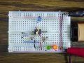
well, i could be wrong but it looks like the middle terminal in the petentiomenter is already hooked up to one of the other terminals, judging by the diagram. but what ya'll are saying makes a little sense. i did also mention that i did a lot of twising of its screw back and forth.

maybe there's too much resistance in the circuit?

and i think tonight i'll try to do a cleanup of the board and lay the wires down flat so a map can be more easily seen from above the circuit.
 

Wendy

Joined Mar 24, 2008
23,421
Leading question, what does the schematic show?

The schematic is a blue print for the actual project.

Bought a new protoboard, build continues.
 

Thread Starter

hillshaveeyes57

Joined Sep 12, 2012
16
so i'm looking at the blueprints online again for the 50ith time. when i did a printout of the circuit the first time is was in black and white and i had assumed the the darker of the two leads going into the board was the negative wire. seems i was wrong. it's an honest mistake and i'll try it the right way when i get home. could i have ruined anything by hooking it up the opposite way?
 

Wendy

Joined Mar 24, 2008
23,421
Yep, done that lots. The 555 in general is very unforgiving about polarity connections. You know when the part gets hot you are out between 35¢ to $1. I buy them in bulk. :D

Sorry I haven't finished the pictures yet. Bought the last unit Tanner's had Saturday, then bought 5 more here...

http://www.summitsource.com/steren-...9.html?ref=1&gclid=CLLokZ7D4LICFeuiPAodRkcAYg

Never used this company before. I'll let you know how it goes.

Seems all the local sources have dried up, Radio Shack doesn't carry them anymore, neither does Fry's. Strange.
 

tracecom

Joined Apr 16, 2010
3,944
Here's my breadboard of Bill's circuit: http://www.allaboutcircuits.com/vol_6/chpt_8/3.html

It works!

When the resistance of R4 goes below about 140Ω, the alternation is too fast to see, and both LEDs appear to be lit. And when R4 goes above 5kΩ, the decrease in flash rate is very slow. From a strictly visual standpoint, changing R4 to a 5kΩ pot and R3 to 150Ω makes the circuit more responsive. And using a one-turn trimmer for R4 further increases the responsiveness. Of course, these changes also decrease the range and the resolution of the circuit. It's a good learning exercise.
 

Attachments

Last edited:

Thread Starter

hillshaveeyes57

Joined Sep 12, 2012
16
i also noticed the 9v i had hooked it up to was getting heated in just a matter of seconds. the polarity of the circuit is def important.

i'll be rebuying the pentometer and the 555 looks like. see how it goes then.
 
Top