 Facebook
 Google
 GitHub
 Linkedin
Hi guys,
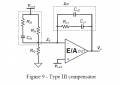
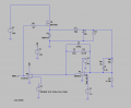
I'm trying to design a buck converter with a PWM voltage feedback loop.I put an image of my circuit in the linked files. To do this design I followed the procedure proposed in the following document :
https://www.infineon.com/dgdl/an-1162.pdf?fileId=5546d462533600a40153559a8e17111a
I put the image of the topology in a below picture.
My buck has the following parameters :
Vin=10V; Vout=5V;
For a reason I'm not sure to understand, my circuit is not working. My output voltage is not going to 5V. Furthermore, the error voltage that goes out of the error amplifier always seems to be the rail as if this amplifier was not doing its job.
My PWM is thus always constant with a constant duty cycle.
My output results are also linked in a picture linked in this post.
Does anyone have an idea of what could be going wrong in my circuit ?
Thanks a lot guys !
Attachments
-
 19.7 KB Views: 12
 -
 23.1 KB Views: 14
 -
 98.5 KB Views: 11


