Buck converter steps down voltage but does not step up current

Thread Starter

mugheesnawaz

Joined Dec 10, 2014
10
Hi all.
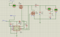
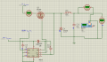
i am designing buck converter to step down 24 volts to 12 volts to charge a battery.
so far i am successful in stepping down the voltage but the main issue which i am facing is that input current is higher than output current which should be the other way around.
i am using ir 2112 as gate driver.kindly tell me where i am wrong because buck converter should step down voltage and step up current.attached is the simulation of the circuit
 

Attachments

Thread Starter

mugheesnawaz

Joined Dec 10, 2014
10
Oh yes,i cant believe i just did that :| obviously it would give 1.34 Amps.
Now the problem i face is i want to compare buck converter's input current and output current to verify if it doest step up current or not.

I have replaced resistor with battery and battery has zero resistance due to which i get MAX current.i want the method to verify on simulation that the current steps up.
 

Attachments

kubeek

Joined Sep 20, 2005
5,794
Why not just use a smaller value resistor to get the desired load current, and then measure the input current?
 

crutschow

Joined Mar 14, 2008
34,285
I don't understand your circuit.
You have no drive signal to the LO (synchronous rectifier MOSFET). :confused:

You might want to reduce the inductance value to increase the load current.
The inductance only affects the ripple current, not the maximum current.
 

Thread Starter

mugheesnawaz

Joined Dec 10, 2014
10
Basic buck converter steps up current and steps down voltage.now if i replace the low side switch with schottky diode,the result is the same.so that is not the issue in simulation.all i am worried about is that input current is higher than load current which is basic violation of buck converter.am i doing something wrong?

if anyone has proven simulation of buck converter working then i will be very thankful.if i am doing something wrong then plz guide
 

Attachments

crutschow

Joined Mar 14, 2008
34,285
In the first circuit (with resistor load) put some ammeters in other parts of the circuit to help determine where the current is going (such as in series with Q2's drain) since it has to be going somewhere.
You also need to look at the circuit with an oscilloscope (voltage versus time) to better understand what's happening.

The second circuit will draw high current, as shown, since it is running open loop into a load with zero resistance.
To charge a battery you need something to limit the current such as a small series resistor.
 

Alec_t

Joined Sep 17, 2013
14,280
Basic buck converter steps up current and steps down voltage.
No, it doesn't.
Consider a converter with 100% efficiency, Vin, Vout, average input current Iin, average output current Iout and d% duty cycle.
Average input voltage = Vin x d.
Average input power Pin = Vin x d x Iin.
Average output power Pout = Vout x Iout = (Vin x d) x Iout.
But Pout = Pin,
∴ Vin x d x Iout = Vin x d x Iin
∴ Iout = Iin.
 

Wendy

Joined Mar 24, 2008
23,415
Buck converters of this type are not my strong suite, but shouldn't the voltage sense be on the other side of the inductor?
 
No, it doesn't.
Consider a converter with 100% efficiency, Vin, Vout, average input current Iin, average output current Iout and d% duty cycle.
Average input voltage = Vin x d.
Average input power Pin = Vin x d x Iin.
Average output power Pout = Vout x Iout = (Vin x d) x Iout.
But Pout = Pin,
∴ Vin x d x Iout = Vin x d x Iin
∴ Iout = Iin.
Alec, I'm no power-supply expert, but I've been using and studying switching power supplies for a decade now and I've never seen formulas like those. What I do know is that current and duty cycle don't have a linear relationship in the least.

These are current-pump devices, so your average input voltage and power assumptions are just not valid. You need to look at total current in and total current out which is described by much more complex math because of the way it changes dynamically during the charge-pump cycle.

But don't believe me. Look at the Wikipedia page. Their first line "A buck converter is a voltage step down and current step up converter" pretty much says it all but they have the math there to back it up.

https://en.wikipedia.org/wiki/Buck_converter
 
Buck converters of this type are not my strong suite, but shouldn't the voltage sense be on the other side of the inductor?
A regulator voltage feedback line SHOULD be on the other side of the inductor. But the VS line of the IR2112 is a high-side voltage-sense fault line. This regulator has no feedback and is therefore an unregulated, duty-cycle-defined charge pump which will have runaway voltage. If you want a regulator, I suggest you steer away from the IR2112. It is not made for this.

mugheesnawas:

Your biggest problem is that you've grounded LIN. It must be driven opposite HIN in order to get the switching characteristics you want. I don't believe the low-side driver is ever coming on. You should use other means to drive your transistors, which is easy if it's only 24V. The IR2112's floating drive circuit is made for high-voltage switching where it's really hard to drive the high side.

That being said, here's an article that uses an IR2110 and an MCU to make a buck regulator. You'll notice he doesn't use the low-side drive, just a Schottky, and he has one critical piece that you're missing -- a voltage feedback path to the MCU so actual regulation can occur.

http://microcontrollerslab.com/buck-converter-using-pic-microcontroller-ir2110/
 
Oh, yeah, you'll get some low-side switching through the substrate diode of the low-side FET.

This should work as a charge-pump but to get optimal current output you're going to have to optimize the duty cycle. You never told us what duty cycle you were using. With the wrong duty cycle or frequency, you could seriously cripple the efficiency of the device and eliminate any current gain you could get.
 

Thread Starter

mugheesnawaz

Joined Dec 10, 2014
10
Thank you all for your kind replies.I replaced the low side mosfet with schottky diode and used a battery of 12V which had internal resistance of 0.1.so i got I_input=I_output. i am using 25khz frequency with 55% duty cycle.input is 24V.
so i should be getting stepped up current which isnt the case.can some one enlighten me who has practically done.my whole point is, does buck converter step up current? i wanted to see that in simulation.
 

Attachments

kubeek

Joined Sep 20, 2005
5,794
That current you see, is it peak, or average, or rms, or something else? Please use an oscilloscope to see what is actually happening.
 

crutschow

Joined Mar 14, 2008
34,285
No, it doesn't.
Consider a converter with 100% efficiency, Vin, Vout, average input current Iin, average output current Iout and d% duty cycle.
Average input voltage = Vin x d.
Average input power Pin = Vin x d x Iin.
Average output power Pout = Vout x Iout = (Vin x d) x Iout.
But Pout = Pin,
∴ Vin x d x Iout = Vin x d x Iin
∴ Iout = Iin
No. the average output power is (Vin x d) x Iin not (Vin x d) x Iout.
You are begging the question to arrive at the answer.
Yes Pout = Pin
∴Vin x Iin = Vout x Iout
∴Iin ≠ Iout (average values)
 
Last edited:

crutschow

Joined Mar 14, 2008
34,285
As kubeek said, we need to see the voltage and current waveforms to know what's going on. A dc ammeter tells only a small part of the story. Without that we're basically blind and going in circles.
Do you know how to display the voltages and currents in the simulation, as an oscilloscope does?
 
Top