Buck converter based LED power supply

Wendy

Joined Mar 24, 2008
23,798
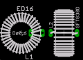
Yep, I do, though the torrid is an attractive option. What do you envision the footprint for a PCB would look like? How would it be mounted, with glue (such as a hot glue gun) or use two ends of the wire on opposite sides of the donut and use it to hold them in place.
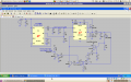
 

SgtWookie

Joined Jul 17, 2007
22,230
You can mount them horizontally or vertically. Vertical mounting gives better air circulation for more cooling and has a smaller board "footprint". Horizontal mounting is more mechanically robust where shock/vibration might be of concern.

Here are a couple of examples:


Toroids are somewhat fragile; they'll shatter if you drop them from a height of several feet onto a hard surface, and can get chipped fairly easily.

Hot glue will work OK. Low-expanding foam (like for insulating door jambs) works well, too - and is very light weight.

The footprint for vertical would be the toroid's height, and the wire's width on either side. The long dimension would be perhaps 4x the wire's diameter plus the toroid's OD; it's tough to hand-wind toroids and have the wire be perfectly flat against the outside.

For horizontal, the OD plus ~4x the wire's diameter. One wire end would be on the inside of the toroid, one on the outside, in a line that intersects the center of the toroid.
 

Attachments

Last edited:

Wendy

Joined Mar 24, 2008
23,798
Not at all. I was also after a wide power supply range, but that isn't always achievable. One of my future projects is to pick your brains (on another thread) about your 5V SMPS regulator. It is the sort of simplicity I like, but a couple of details elude me.

Love your site.
 

Thread Starter

tom66

Joined May 9, 2009
2,595
Here's my synchronous buck current-controlled design. It is capable of outputting around 2.5A at up to 4.7V (~11.75W.)

Being synchronous brings the advantages of no Schottky diode.

  • Higher efficiency: Rds(on) of ~0.02Ω vs. constant ~400mV drop.
  • Higher output current in a smaller size, making the supply smaller.
However synchronous designs cost more and are more difficult to design, so it's a trade off.

It is based around two chips: LTC4449, a MOSFET driver (dual N-ch high and low side) and a high speed dual comparator, LT1720. (The comparator can be replaced by any high speed comparator but this was in the library.) It's self-resonant, like the original circuit, requiring no dedicated oscillator. It's also limited to 4.7V out, to prevent damage to reverse biased LEDs (that's the function of the second comparator.)

It's very similar to the original design, except because it uses a dedicated MOSFET driver, it can eliminate several components. The gate driver handles driving the fets with high gate currents, as well as handling the dead time. It is however only suitable for surface mount designs, as the driver is only available in SMT packages. This, however, is a good thing because it allows for more powerful SMT fets. Unfortunately it's only in a 2x3 DFN, which is tricky to solder.

The 4.7V supply is generated using a zener. I might replace this with a compact switching buck, like LTC3642. The zener+resistor dissipates a considerable amount of power. The design requires about 50mA to run the gate driver.

Due to the N-channel fets and synchronous design it is capable of operating up to 35V input (38V maximum.) The fets are rated for 7.5A drain current which is probably overkill: smaller fets can be used. It will also operate down to around 7V even with non-logic fets, due to the boosting feature of the gate driver. At lower voltages it takes longer to start up, up to 100ms at 7V.

Currently there is no slow start mechanism. The LED gets hit by the full current the supply is set for after the regulator has started up, however, output RMS current is constant after start up. I am still considering on how to implement this.

I'll see about designing a PCB around this or a similar design.
 

Attachments

SgtWookie

Joined Jul 17, 2007
22,230
Hi Roman,
Thanks for joining in!

I simulated your circuit using LTSpice; and found that the current through the LEDs varies with the supply voltage.

I had to reduce the inductor to 33uH to get it to be pretty stable over the supply voltage range, it would get a bit wacky at 330uH. C2 would drive Q1's be junction quite negative; it does so even now, but it's under -5v at 15v so that's OK.

Anyway, to correct the variation in current over a range of Vcc, the current sense resistor R4 would have to be "in the loop" at either end of L1, or between the junction of Vcc/D1 and C4/LED1. That means double the losses in R4, but current would be stable over the range of voltage.
 

Attachments

SgtWookie

Joined Jul 17, 2007
22,230
Tom66,
Looks like your simulation isn't quite ready to go to a PCB yet.

Why don't you upload the .asc file so we can play with it?
 

Thread Starter

tom66

Joined May 9, 2009
2,595
Hi SgtWookie,

See attached .asc. It contains the current revision. I've swapped the LTC4449 with an LTC4442 because it's available in an easier to solder MSOP-8 package.

This design uses an LTC3631 to generate the 6.5V supply from an input of 6.5V to 35V (the buck can go up to 45V (with automotive surge rating up to 60V), but the driver is only rated for 38V max.) The LT1720 high speed dual comparator is specified for up to 6V, so a different one will need to be used in the final design. Although common-mode range for it is only to Vcc-1.2V, it specifies that it is possible to operate one of the inputs outside of this range as long as the other input is within the rated range. I've been eyeing up the LT1715 as another option. What do you think about comparator speed - how important is it?

I've also added a power good output. During startup this is high. However if the supply does not stabilise within the required time it falls low. The overvoltage comparator is used for this, because if the supply's current is too low, it will try to increase output current. PWRGOOD could be used to indicate a fault condition - perhaps an LED might light during a failure. Usually, the supply will continue oscillating in a fault condition, but the output does not reach the set point. In some cases (e.g. direct shorts) it can shut down completely and require a reset. If this happens, I'd like to find a way to automatically reset the supply. Screenshot #2 shows the supply in a failure condition, screenshot #3 shows it sucessfully starting and driving an LED. The ripple on the power good line is due to the 6.5V supplies' ripple.

One of the other things I was thinking of adding were two optocouplers: one would turn the supply completely on and off, and the second one would allow pulse width modulation of the voltage reference and thus adjustment of the output current.

Also, I was thinking of adding high-side current sensing, instead of low-side sensing. High-side sensing allows detection of output shorts to ground. Any ideas on how to implement this? I was thinking of an op-amp set up as a differential amplifier, but there's probably a better and lower cost way of doing this.

Slow start is still under consideration. I am struggling to get it to slow start. It hits the LED with a high level of current on start up before it stabilises.
 

Attachments

Last edited:

SgtWookie

Joined Jul 17, 2007
22,230
eblc1388,
Take a look at your gate waveform and the MOSFET power dissipation; not so good.

The function of C2 was to provide some feedback to snap Q1 on and off, so that M1's gate charge/discharge resembled more or less a square wave. Without C2, M1 spends a lot of time in the linear region dissipating power as heat.
 

Wendy

Joined Mar 24, 2008
23,798
I've got the first board etched, if I can keep from screwing it up drilling I'll be good to go. The pattern transfered perfectly, something I have alot of trouble with. The 2:1 of hydrogen peroxide and muriatic acid worked like a treat. I used gloves of course, and q-tips to wipe it while it was etching. Took less than 5 minutes, and the toner wiped off without a mark.

While I was in Tanner's I bought some ¼W 5.1V zeners and a laminator for future etching projects. The laminator is a $30 gamble, I'll let you know.
__________________________

Drilling is done. So far so good. I'm using tools I've had for a very long time, but never used. Like the specialty drill set. I used the 0.035 drill bits. I'm not sure what the standard is.
 
Last edited:

eblc1388

Joined Nov 28, 2008
1,542
eblc1388,
Take a look at your gate waveform and the MOSFET power dissipation; not so good..
You're right. Missed that.

Though the current regulation is good, the heat dissipation of the MOSFET is too great.

I found that the NPN transistor has been turned off by the snap action and subsequent current limiting function will then be bypassed as the transistor is already turned off before the current limit has a chance to do so.

By adding another transistor to turn off the MOSFET early, the current regulation now works as expected. The switching waveform of the MOSFET is between 0 and VCC(green trace in 1st image) so the MOSFET spent less time in linear mode.


Attachments

Last edited:

iONic

Joined Nov 16, 2007
1,662
I've been quietly monitoring the development in this thread for some time. It's fascinating how much some of you know, thus how little I know!

Not to throw the topic of in some wild tangent, but does anyone understand how the "Buck-Puck" works...anyone grind one down and reverse engineer it?

Buck-Puck
 

Thread Starter

tom66

Joined May 9, 2009
2,595
I've been quietly monitoring the development in this thread for some time. It's fascinating how much some of you know, thus how little I know!

Not to throw the topic of in some wild tangent, but does anyone understand how the "Buck-Puck" works...anyone grind one down and reverse engineer it?

Buck-Puck
For the lowest cost it may be based around a dedicated LED controller IC, e.g. one of these http://www.national.com/analog/led.
 

Thread Starter

tom66

Joined May 9, 2009
2,595
Agh, for some reason I just figured out my supply isn't working properly (for some reason it is only using linear regulation) - might want to ignore my latest post with the buck supply... I'll try to get another one working.
 

Wendy

Joined Mar 24, 2008
23,798
Actually what I am trying to make is a direct equivalent. Got the drilling done, now to put the other graphic on the other side, then the soldering starts again.
 

SgtWookie

Joined Jul 17, 2007
22,230
Tom66,
I did a hack-n-slash on your schematic; changed how the reference voltage was being developed; you had V4 as the source which was causing problems, I now have it being derived from V+.

I also changed C2's ground to be the low side of the LED; this couples the output of the synchronous rectifier to Rsense (R2), which gives a more immediate feedback, preventing the large overshoot that you were seeing. Added a 2nd filter cap to the output of the synch. rectifier.

Added a more-or-less low-pass filter to the input of the comparator, which keeps it from toggling at a high frequency.

Deleted the "output good" stuff. Changed the resistors on your voltage regulator to get ~5v out.

Anyway, now you have something a bit closer to what you wanted. Have at it.
 

Attachments

Thread Starter

tom66

Joined May 9, 2009
2,595
Tom66,
I did a hack-n-slash on your schematic; changed how the reference voltage was being developed; you had V4 as the source which was causing problems, I now have it being derived from V+.

I also changed C2's ground to be the low side of the LED; this couples the output of the synchronous rectifier to Rsense (R2), which gives a more immediate feedback, preventing the large overshoot that you were seeing. Added a 2nd filter cap to the output of the synch. rectifier.

Added a more-or-less low-pass filter to the input of the comparator, which keeps it from toggling at a high frequency.

Deleted the "output good" stuff. Changed the resistors on your voltage regulator to get ~5v out.

Anyway, now you have something a bit closer to what you wanted. Have at it.
Great! Looks good. Is there any chance of adding in the overvoltage protection? Most LEDs are fried by a reverse voltage of more than 5V. It could be an option for higher voltage arrays.

Also, I was experimenting with my original design and found it worked much better with low capacitances. I tried capacitances of 220nF and current ripple is much lower - it also starts up slower. You can't lower it to zero capacitance as it won't oscillate, but you can make the capacitance very low (limit is around 100nF.) This would allow for small ceramic output capacitors, and ceramic capacitors are much more reliable, and often smaller - also, the higher frequency operation probably brings some more advantages.
 

SgtWookie

Joined Jul 17, 2007
22,230
Is there any chance of adding in the overvoltage protection?
Why? The current only flows one way; through the LED(s). If the LED(s) opened up, then you'd have the synchronous buck running wide open, but the output current wouldn't have anyplace to go - so no damage.

Most LEDs are fried by a reverse voltage of more than 5V. It could be an option for higher voltage arrays.
I don't see how the LEDs could get a reverse voltage across them, unless someone hooked up the power backwards. That would be a major facepalm.

Also, I was experimenting with my original design and found it worked much better with low capacitances. I tried capacitances of 220nF and current ripple is much lower - it also starts up slower. You can't lower it to zero capacitance as it won't oscillate, but you can make the capacitance very low (limit is around 100nF.) This would allow for small ceramic output capacitors, and ceramic capacitors are much more reliable, and often smaller - also, the higher frequency operation probably brings some more advantages.
Well, go ahead and experiment with it. I just wanted to give you a starting place where things were more or less working without blasting the LED on startup, which you seemed to be having some difficulty with.
 

Thread Starter

tom66

Joined May 9, 2009
2,595
Why? The current only flows one way; through the LED(s). If the LED(s) opened up, then you'd have the synchronous buck running wide open, but the output current wouldn't have anyplace to go - so no damage.

I don't see how the LEDs could get a reverse voltage across them, unless someone hooked up the power backwards. That would be a major facepalm.
Yeah, I want to protect against LEDs being put in reverse. I've done this with signal LED's too much to not really worry about it - but a more expensive LED array wouldn't be on my list to blow up.

Well, go ahead and experiment with it. I just wanted to give you a starting place where things were more or less working without blasting the LED on startup, which you seemed to be having some difficulty with.
Thanks. The problem with the smaller caps are the LED gets hit by a high current on startup. But, I found with a 2.2μF cap across the LED and a 220nF to ground works very well, and prevents the high current surge. You can get 2.2µF 16V caps in 0603.

Also, I noticed you dropped the supply to 5V. This isn't going to work, or if it does, the efficiency will be poor. The synch. driver is only rated 6V - 9.5V on the Vcc and Vlogic lines. I'm replacing the supply with 7.5V, and am probably going to find some high voltage high speed comparator to run off this same line (any suggestions?)
 

Attachments

Last edited:
Top