 Facebook
 Google
 GitHub
 Linkedin
Help please. I have an older drill. The reverse switch blew, so I want to make it a single direction drill. Not sure how to wire it up. Thanks
Attachments
-
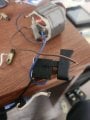 1.4 MB Views: 12
 -
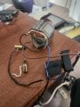 1.7 MB Views: 12


