Broken NewAir AW-321ED Wine Cooler

Thread Starter

richl705

Joined Dec 31, 2025
7
Hello all,
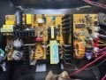
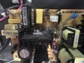
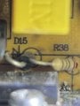
First post here. Hoping someone can help out. I have a Newair AW-321ED Wine Cooler. One side stopped working so I opened up the back. The PCB is "PCB80812K1" (picture IMG_5965). Made a couple mistakes at this point. Determined the glass fuse had blown. It was marked 25A/250V so I put one in (I work on cars mostly...). I reinserted the power to the board but the main power was still on. At that point there was a flash and I released the magic, blue smoke from the item that is a "green disk." Pieces went everywhere. The description on the PCB for the Green Disk is "RTC" but it doesnt appear to actually be a Real Time Clock, perhaps a part of one. I then took a picture of the fuse label and zoomed in and it was actually 2.5A/250V for the fuse. Now I have a blown fuse and a destroyed green disk widget. What I am thinking is to remove the old Green Disk and solder in a new one. Issue is I dont know the proper name for the Green Disk widget or where one orders them these days.

So in a nutshell, what is the Green Disk widget and where can I buy one?

Appreciate any help,
Richard

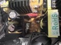
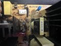
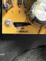
Picture IMG_5956 shows the fuse and just below the left hand side of the fuse is where the green disk widget used to be.
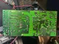
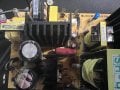
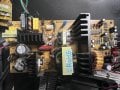
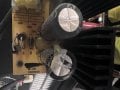
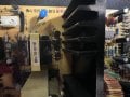
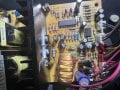
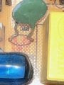
Pictures IMG_5963 and 5964 show the green disk widget currently on the other PCB which still works.
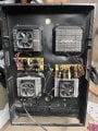
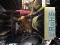
Picture IMG-5965 shows the name of the PCB
 

Attachments

MrChips

Joined Oct 2, 2009
34,628
Welcome to AAC!

Usually, when the fuse or anything blows, it blows for a reason. Just replacing the fuse can cause more than the initial item to blow. It usually requires one to diagnose possible problems before applying power.

The green disk is surely not a Real Time Clock. It is more likely a surge protection device. Replacing that alone will not solve the problem.

Can you post photos showing the board in full, on both sides?

Edit: Here are a couple links on AAC. If you posted photos of the board we may be able to see the condition of the components on the board.
https://forum.allaboutcircuits.com/threads/another-broken-newair-aw321ed-wine-fridge.206125/
https://forum.allaboutcircuits.com/...moelectric-cooler.101748/page-14#post-1430741
 

MrChips

Joined Oct 2, 2009
34,628
The green component with the ID board marking of RTC is a surge suppressor, possibly NTC 5D-11.
It is blown (or the fuse blows) because there is still a problem on the board. You have to find and fix the true cause first.
Look for shorting semiconductor devices on the heat sinks.
 

Thread Starter

richl705

Joined Dec 31, 2025
7
Thanks very much for the follow up and the links. I had found the first link you provided previously but not the second link. A lot of detail in there. I am hoping mine is not as complicated a fix. I should add some context that didnt occur to me until you mentioned other factors playing in. A few months back I had some concrete work done in the basement a few feet from the cooler. When I went to open up the back yesterday I noted the screens that cover the fans were completely blocked with concrete dust. I vacuumed that all out. That probably put some pressure on the system as well. Below are three pics of the unit and the front and back of the PCB. Thank you for your time
 

Attachments

Thread Starter

richl705

Joined Dec 31, 2025
7
I retook some pics and zoomed in a bit especially around the heat sinks on the board. Dont see anything obviously burned. Seems like in picture 5973, where the vertical screw is, the two transistors above it may not be in good shape? Pic 5982 is zoomed into that area and it really doesnt look too bad but not sure.
 

Attachments

MrChips

Joined Oct 2, 2009
34,628
Here is a partial schematic that might be similar to your board.
The first items to be checked are D13, D14, D16, D17. Then move on to D11, D15, D10, D12, TR6, TR7.
Are you comfortable reading schematics?
Do you know how to test diodes and transistors using DMM?


1767293316582.png
 

Thread Starter

richl705

Joined Dec 31, 2025
7
Although I re-wired an entire 1958 MGA I have never checked transistors on my multi-meter. Time to learn. I will take a look and start with the sequence you provided. Thanks much
 

MrChips

Joined Oct 2, 2009
34,628
For testing components while still in circuit, note that the measurement is dependent on everything else that is in the circuit. Hence the results of the measurement must take that into consideration.

How to measure a diode with a DMM

Set the DMM to diode test mode.
With red meter probe at the anode, you should see the forward diode voltage, about 0.6 V.
Reverse the probes and you should see an open circuit (high resistance). With the diode still in-circuit, you may see a finite resistance.

Diode test.jpg
 

wayneh

Joined Sep 9, 2010
18,087
It was marked 25A/250V so I put one in (I work on cars mostly...).
You've probably learned a valuable lesson here but I just wanted to add some perspective.

You'll almost NEVER see a fuse over 15A in anything you'd place in your home. Depending on where you live, appliances are limited to the max safe current in the home wiring. In the U.S., wall receptacles and lighting circuits are protected by a standard 15A circuit breaker. That caps the maximum power of appliances at about 120V x 15A = 1,800W. Anything more than that will trip the breaker. So there's no point to a 15A or larger fuse in a plug-in appliance.

Occasionally you'll see a 20A circuit designed to support, for example, a space heater or other high-draw appliances. An electric range or air conditioner will also have a higher capacity (and voltage) circuit but typically there will not be any wall receptacles on such a circuit except the one at the relevant appliance.

Yes, the concrete dust may have contributed to the failure. The cooler I repaired had a fan that had seized up.

I'm frankly not optimistic about repairing your board - you zapped it pretty hard. Have you looked at all for a replacement board? That said, having a working board in parallel means you have a reference for measuring voltages and such. That might help.
 

Thread Starter

richl705

Joined Dec 31, 2025
7
Excellent. Thats great info. You are probably right about replacing the entire board. I will see whats available and given time involved etc it may be better just to put in a new board.
 

MrChips

Joined Oct 2, 2009
34,628
It might be expedient to install a new board. But if you want to take an adventure in electronics diagnostics, get out the the DMM and start doing some testing.

A word of caution. When you see large electrolytic capacitors on a board, it is a good idea to discharge the capacitors through a low value resistor (10 - 100 Ω) before probing.
 

Thread Starter

richl705

Joined Dec 31, 2025
7
I will do that and thanks again for taking the time to work with me. I really appreciate it. Will let you know how it goes. Best, Richard
 

Thread Starter

richl705

Joined Dec 31, 2025
7
MrChips, I continue to search for a replacement PCB but in the meantime I have tested most of the resistors you listed. Some I could only get to the soldered side. A few I measured both ways because the number was so high I wasnt sure if I had the red on the anode or not:

D13 747/1445 (one side on soldered side)
D14 745/1450
D16 004
D17 004

D11 746/1437 (read from soldered side)
D15 (not found)
D10 808/1346
D12 025
TR6 (not found)
TR7 (not found)

I am assuming the high numbers are bad but wanted to check with you. Will continue to look for a replacement PCB. Thanks
 
Top