 Facebook
 Google
 GitHub
 Linkedin
Be gentle with me fellas. I'm new to this whole PCB repair thing. A friend was gonna throw away this NewAir wine fridge because the right side of the fridge had failed. I said I'd take a crack at it and here I am. So here we go.
Upon plugging in the fridge. The left side of the fridge has proper temperature display and interior lights, fans are spinning, and the red and green LEDs on the board are lit. All is well. The right side, temperature display is on but not showing numbers correctly, interior lights work, neither fan is spinning, and only the red LED on the board is lit.
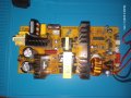
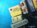
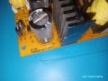
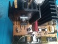
Inspecting the questionable board reveals a single bulged capacitor. A replacement is ordered and installed. I plug the connections back in and give it power, it blows the big glass fuse. I unplug all connections except power and install a new fuse. This time I make one connection at a time. Everythings looking good. I have both LEDs, front display, interior lights, fans are spinning. I make the last connection, which was one of the wire connections, and the fuse blows again. So I disconnect my last connection, replace the fuse, power it on and.... no LED lights and one of the transistors actually popped. Thank goodness for safety glasses. So today I replaced the popped transistor and the C8 capacitor ( I read on a bunch of threads here that the C8 seems to go bad often.)
I put the board back in the fridge and connect power only, plug in the cord and I get nothing, no LED lights, no voltage at the glass fuse, nada. Seems to be stone dead. I did put my probes into the power connector and it's showing 120v so it's definitely the board.
I'd order a replacement board but alas I can find none and I do not know where to go from here with this repair. I've inspected the board front and back and can see nothing obvious to my amateur eyes. It's my first time and my only training has been YouTube and this forum. Any advice would be appreciated.
Attatched are some pictures of the board. You can see the bulged capacitor and the later popped transistor.
Upon plugging in the fridge. The left side of the fridge has proper temperature display and interior lights, fans are spinning, and the red and green LEDs on the board are lit. All is well. The right side, temperature display is on but not showing numbers correctly, interior lights work, neither fan is spinning, and only the red LED on the board is lit.
Inspecting the questionable board reveals a single bulged capacitor. A replacement is ordered and installed. I plug the connections back in and give it power, it blows the big glass fuse. I unplug all connections except power and install a new fuse. This time I make one connection at a time. Everythings looking good. I have both LEDs, front display, interior lights, fans are spinning. I make the last connection, which was one of the wire connections, and the fuse blows again. So I disconnect my last connection, replace the fuse, power it on and.... no LED lights and one of the transistors actually popped. Thank goodness for safety glasses. So today I replaced the popped transistor and the C8 capacitor ( I read on a bunch of threads here that the C8 seems to go bad often.)
I put the board back in the fridge and connect power only, plug in the cord and I get nothing, no LED lights, no voltage at the glass fuse, nada. Seems to be stone dead. I did put my probes into the power connector and it's showing 120v so it's definitely the board.
I'd order a replacement board but alas I can find none and I do not know where to go from here with this repair. I've inspected the board front and back and can see nothing obvious to my amateur eyes. It's my first time and my only training has been YouTube and this forum. Any advice would be appreciated.
Attatched are some pictures of the board. You can see the bulged capacitor and the later popped transistor.
Attachments
-
 4.1 MB Views: 19
 -
 2 MB Views: 18
 -
 3.8 MB Views: 16
 -
 1.3 MB Views: 15


