Facebook
 Google
 GitHub
 Linkedin
I am working on a project to use a single output to change the state of a latching solenoid (magnetic retention one direction, spring retention opposite, no holding power required)
So far I have the 3 elements of the circuit breadboarded, but I am running into an issue for the final enable. At this stage, all transistors are BJT.
1. Direction is controlled by a sequential switching bistable multivibrator circuit. See http://www.electronics-tutorials.ws/waveforms/bistable.html (The current orientation is irrelevant, it is verified through another means an can alternate until the desired result is achieved)
2. Timing is controlled by a (2) sequence 555 timer. First timer triggers off the same input controlling the multivibrator and is on long enough to ensure everything is ready to energize the motor (For test, 5 seconds). Upon completion of the first timer, the second timer triggers an H-bridge to energize the solenoid for a pre-defined length of time (For test, 5 seconds). See http://www.gadgetronicx.com/sequential-process-control-ic-555/
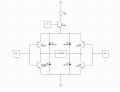
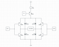
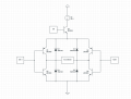
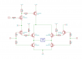
3. An H-bridge to energize the solenoid in the direction controlled by the multivibrator, for the duration from the timer. See https://electrosome.com/dc-motor-driving-using-h-bridge/
TL;DR
I am running into an issue "enabling" the H-bridge. My initial thought was to have a high-side NPN transistor acting as a switch to the H-bridge, but it doesn't seem to work. I suppose I could AND the signal from the direction controller and the timer on the base of the H-bridge, but that would substantially increase chip count. When I get near a scanner, I can add some circuit sketches, but the links were the starting point.
So far I have the 3 elements of the circuit breadboarded, but I am running into an issue for the final enable. At this stage, all transistors are BJT.
1. Direction is controlled by a sequential switching bistable multivibrator circuit. See http://www.electronics-tutorials.ws/waveforms/bistable.html (The current orientation is irrelevant, it is verified through another means an can alternate until the desired result is achieved)
2. Timing is controlled by a (2) sequence 555 timer. First timer triggers off the same input controlling the multivibrator and is on long enough to ensure everything is ready to energize the motor (For test, 5 seconds). Upon completion of the first timer, the second timer triggers an H-bridge to energize the solenoid for a pre-defined length of time (For test, 5 seconds). See http://www.gadgetronicx.com/sequential-process-control-ic-555/
3. An H-bridge to energize the solenoid in the direction controlled by the multivibrator, for the duration from the timer. See https://electrosome.com/dc-motor-driving-using-h-bridge/
TL;DR
I am running into an issue "enabling" the H-bridge. My initial thought was to have a high-side NPN transistor acting as a switch to the H-bridge, but it doesn't seem to work. I suppose I could AND the signal from the direction controller and the timer on the base of the H-bridge, but that would substantially increase chip count. When I get near a scanner, I can add some circuit sketches, but the links were the starting point.