Facebook
 Google
 GitHub
 Linkedin
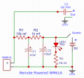
A simple bipolar transistor amplifier gives a gain of 30dB but with 1% distortion. A TL071 transimpedance amplifier gives 33dB gain but with no increase in distortion over that resulting from the JFET.View attachment 316642
Beau Schwab Electret Mic Preamp
- Thread starter oneoldude42
- Start date