Beau Schwab Electret Mic Preamp

Thread Starter

oneoldude42

Joined Feb 19, 2024
23
Hi All,

I am interested in a simple measurement mic preamp for use in testing speakers. I found this unusual circuit online and would like opinions on it.

In 2015 Beau Schwab, at: phttps://forums.parallax.com/discussion/163067/microphone-preamp , posted the following,
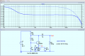
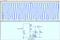
"Try this one for simple ... This is of my own design using an Emitter follower configuration and a self biasing technique to place the transistor in it's most sensitive linear region (exactly where you want it for an Audio pre-amp). The idea is that the 10uF Capacitor trickle charges through the 10k and the 47k until it reaches a point that the transistor turns ON. By turning ON, the trickle power is quenched causing the transistor to turn OFF. A balance is established at the "sweet spot" of the transistor where any perturbation on the Emitter of the transistor is amplified at the Collector of the transistor and in phase with the Emitter.

I have used this circuit with Electret mics with pleasing results. ..."

Here is an image of the circuit. My questions will follow.

1709181882979.png

Here are my questions:
1. Is a 9V supply acceptable?
2. Expected gain of this circuit?
3. Expected freq resp?
4. Expected distortion?
5. Expected noise?
6. Ideal mic capsule for measurement purposes?
7. Will a WM61A work well here?
8. Will this circuit serve well for a measurement mic?

Thanks, ab
 

Ian0

Joined Aug 7, 2020
13,097
It’s a cascode circuit, so I would have expected a fixed voltage bias for the 2N3904.
The output of the microphone capsule is the drain of a JFET, so the output will have high impedance, effectively a constant current source.
The cascode transistor will just pass the constant current from emitter to collector. The voltage gain of a common base circuit is Zout/Zin, so it wont contribute any gain. The resistor from collector to base (because base is a AC ground via the capacitor) will place some additional load on the output, so reduce the signal.
My conclusion: it doesn’t do anything useful.
 

Papabravo

Joined Feb 24, 2006
22,058
I do not understand your simulation. You seem ti have an AC sweep as the supply voltage, and what is U1?
The thread title suggests that it is an electret microphone.

V1 will always have a DC output of +9V. In the .tran sumulation, the AC 1 attribute to V1 has absolutely no effect.
 

ericgibbs

Joined Jan 29, 2010
21,395
Hi,
I hope the TS comes back either to confirm or modify his original circuit.

Trying to inject an AC of 1V including the electret microphone to get a true BW plot is messy!

E
 

Ian0

Joined Aug 7, 2020
13,097
Neither would I. It's already at a high impedance so a common-base stage isn't going to improve things.
 

ericgibbs

Joined Jan 29, 2010
21,395
Not even in a simulator.
Bill,
You seem to have a very closed mind about things you do not use or understand.

I might remind you it is the microphones internal Source to Drain of the FET that is in the Emitter path, not the high impedance capacitive section.

If a TS posts a circuit, the correct action is to use his circuit to demonstrate it's performance, then discuss with him any problems.
E
 

MisterBill2

Joined Jan 23, 2018
27,186
Bill,
You seem to have a very closed mind about things you do not use or understand.

I might remind you it is the microphones internal Source to Drain of the FET that is in the Emitter path, not the high impedance capacitive section.

If a TS posts a circuit, the correct action is to use his circuit to demonstrate it's performance, then discuss with him any problems.
E
Note that I did not state that the circuit would not work. Nor did I say it would not work.. And I am fully aware that it is not in the high impedance portion of the electret mic.
So I suggest that YOU explain to the TS how it works, and what benefit it provides.
 

Beau Schwabe

Joined Nov 7, 2019
186
The simulator is using a 4.7k resistor ... that resistor should be 47k

That said, the circuit works well for it's intended purpose. Imagine for a moment that the transistor is ON and fully saturated. Is it then NOT very similar to the standard way of connecting an electret mic?

I suggest trying the circuit with the transistor and also the conventional approach without the transistor and just see for yourself.

Reference Image: (Conventional setup)
https://electronics.stackexchange.c...-connect-electret-microphone-module-and-opamp
 

ericgibbs

Joined Jan 29, 2010
21,395
Hi @Beau Schwabe
Corrected to use a 47K
Simulation shows a gain of approx 22dB and an acceptable BW.
I agree that a common base amplifier configuration is often used in amplifiers.

Here are my questions:
1. Is a 9V supply acceptable?
Yes
2. Expected gain of this circuit?
~22db at 1k
3. Expected freq resp?
Refer attached plot
4. Expected distortion?
??
5. Expected noise?
non visible on the sim
6. Ideal mic capsule for measurement purposes?
Not sure what measurements you are making?
7. Will a WM61A work well here? If you have a datasheet, please post it.
8. Will this circuit serve well for a measurement mic?
Yes

E
 

Attachments

Thread Starter

oneoldude42

Joined Feb 19, 2024
23
The simulator is using a 4.7k resistor ... that resistor should be 47k

That said, the circuit works well for it's intended purpose. Imagine for a moment that the transistor is ON and fully saturated. Is it then NOT very similar to the standard way of connecting an electret mic?

I suggest trying the circuit with the transistor and also the conventional approach without the transistor and just see for yourself.

Reference Image: (Conventional setup)
https://electronics.stackexchange.c...-connect-electret-microphone-module-and-opamp
Hi
Beau Schwabe and ericgibbs . Thank you for your replies.
To clear up confusion, I would like to make clear the purpose of this thread. I and a host of other DIY loudspeaker builders have been relying on the Conventional Setup circuit (remotely powered) pointed to by Beau. But most all the references relate to the excellent WM61A capsule which ceased production many years ago. I happen to have a couple of those capsules, so I am interested in maximizing their utility. However, the WM61A performance is greatly enhanced re overload when it is biased with 9V through 10K ohms. I guess the improvement would also apply to many other FET electret mic capsules notwithstanding their marketing info re 2-5V supplies. Am I correct in that guess?

Typically, the DIY speaker builder will measure all the normal speaker parameters like frequency resp, distortion, phase, time delay between drivers, etc.
Typically, they will use software like ARTA (paid, my favorite ARTA Software (artalabs.hr)) or HOLM (free, HOLMImpulse (64-Bit) - Free download and software reviews - CNET Download ).
Typically, they will use a remotely powered mic with a 9V battery supply as originally described by Linkwitz over 20 years ago (https://www.linkwitzlab.com/sys_test.htm#Mic). Trouble is the WM61A mics no longer exist. And the Chinese "replacements" for the 61A have been described as "Chinese Trash" on the web.

So, what I am looking for is a remote powered (9V Batt) circuit with a modern readily available elecret mic that can serve to feed a mic in or a line in (switched if necessary) without over driving the mic in or under driving line in and that has a flat freq response (20-20K Hz), low inherent distortion, and low noise for loudspeaker measurements.

Such a circuit would be a revelation to the DIY loudspeaker crowd and perhaps others as well. If we can manage to do that, I will post it all over the DIY world with attribution to the designers (not me) and take the DIY by storm leaving the darkness of ancient history and going into the bright light of modernity.

By the way, are there any modern electret mics that are as good as the WM61A? That is, essentially flat from 20-20K Hz with very low noise and almost no distortion unless overloaded? And will Beau's circuit supply the mic with as much current as the Conventional Setup with a 9V supply and 10kresistor?

Oh, I was asked to provide a data set of the WM61A. It is attached.

And thank you all for your help.
 

Attachments

Ian0

Joined Aug 7, 2020
13,097
Have you considered MEMS microphones? The tolerances are rather tighter than the telephone handset inserts. Neither condensor insert nor MEMS is particularly good for noise, and no preamp is going to remedy that.
A good studio condensor mic is about 10dB to 20dB better.
 

Thread Starter

oneoldude42

Joined Feb 19, 2024
23
Have you considered MEMS microphones? The tolerances are rather tighter than the telephone handset inserts. Neither condensor insert nor MEMS is particularly good for noise, and no preamp is going to remedy that.
A good studio condensor mic is about 10dB to 20dB better.
Thanks for the input. I reviewed them and found too many problems for loudspeaker use. Thanks any way.
 

Ian0

Joined Aug 7, 2020
13,097
I found in my copy of SPICE a JFET called "electret". It has a drain current of 0.5mA @ Vgs=0, so I'm guessing that it's the JFET in a condensor microphone. It's probably one of @Bordodynov 's models.
Here's the results.
Screenshot from 2024-03-01 21-30-07.pngAs you can see, the "amplifier" slightly reduces the signal (mainly due to the loading of R3), and I think my conclusion of "better off without" is valid.
 

Ian0

Joined Aug 7, 2020
13,097
A simple bipolar transistor amplifier gives a gain of 30dB but with 1% distortion. A TL071 transimpedance amplifier gives 33dB gain but with no increase in distortion over that resulting from the JFET.Screenshot from 2024-03-01 21-48-56.png
 
Top