Facebook
 Google
 GitHub
 Linkedin
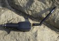
I am working on a micro cat tracker tracker project (GPS / LoRa) with ATSAMR34 MCU with LoRa Transceiver and a u-Blox ZOE-MOQ GPS Receiver powered by three Energizer 675 Zinc Air batteries, which should last about three months when determining the position every hour. The MCU and GPS will be in a sleep mode awaken each hour for about one minute to get valid GPS coordinates. If there will be not GPS signal available within 60 second I will send "no GPS data" LoRa message to allow LoRa network to determine the approximate location.
To achieve the longest battery life, I must use only the necessary components and avoid any current loss (even µA). The battery voltage is 4.4V and MCU and GPS is powered by 3.3V through TI LDO TPS7A0233PDQNR. The PCB size will be about 8 x 35 mm without batteries (sewn into cal collar).
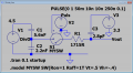
I need to measure the battery voltage to alert the user in the Android application to replace the batteries. That's why I don't like to use the resistor voltage divider and I would like to use the capacitor voltage divider (CVD) with C1 = 5.6nF and C2 = 2.2nF, min. sampling time is 250 ns, 8-bit accuracy, Vref is set to Vcc = 3.3V, CSAMPLE = 2.8pF and RSAMPLE = 1,715 Ohm.
When I tried ADC measurement on the ATSAMR34 Xplained development board and unplug and plug the board to USB port before each measurement I got pretty same ADC results. When the board is still connected, the measured voltage values decrease.
Although I know to use the CVD with ADC is a tricky and I should possible use classic resistor voltage divider switch on by N-MOSFET PMH260UNEH I am not sure about the GPIO pins MCU voltage during sleep mode.
Maybe an Op Amp voltage follower could help me prevent the C2 voltage drop. MAX40023 has Rin 15G, 17µA, <1pA.
What's your thought and suggestion? I have also troubles to simulate it with LTspice.
To achieve the longest battery life, I must use only the necessary components and avoid any current loss (even µA). The battery voltage is 4.4V and MCU and GPS is powered by 3.3V through TI LDO TPS7A0233PDQNR. The PCB size will be about 8 x 35 mm without batteries (sewn into cal collar).
I need to measure the battery voltage to alert the user in the Android application to replace the batteries. That's why I don't like to use the resistor voltage divider and I would like to use the capacitor voltage divider (CVD) with C1 = 5.6nF and C2 = 2.2nF, min. sampling time is 250 ns, 8-bit accuracy, Vref is set to Vcc = 3.3V, CSAMPLE = 2.8pF and RSAMPLE = 1,715 Ohm.
When I tried ADC measurement on the ATSAMR34 Xplained development board and unplug and plug the board to USB port before each measurement I got pretty same ADC results. When the board is still connected, the measured voltage values decrease.
Although I know to use the CVD with ADC is a tricky and I should possible use classic resistor voltage divider switch on by N-MOSFET PMH260UNEH I am not sure about the GPIO pins MCU voltage during sleep mode.
Maybe an Op Amp voltage follower could help me prevent the C2 voltage drop. MAX40023 has Rin 15G, 17µA, <1pA.
What's your thought and suggestion? I have also troubles to simulate it with LTspice.
Attachments
-
 59.6 KB Views: 34
 -
 44.8 KB Views: 34
 -
1.5 KB Views: 3