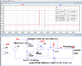
Changed many things. Slowed it down. Ron=100 ohms to not suck the battery down. Cap = bigger.
Measure the time it takes for the voltage to charge back up to 2V. The time is related to C, R and Battery voltage.
The "my switch" is a pull down MOSFET or IO port pin.
I don't have the CA3140 in ...\Documents\LTspiceXVII\lib\sym\OpAmps but in Bordodynov library Sborka.lib in ...\Documents\LTspiceXVII\lib\Bordodynov\lib\sub
Maybe it could help me if you can copy here the lib description for CA3140 from your lib file. E.g.:
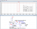
Please can you post a detail graph with single red spike V(n003)? I have SPICE model of the MAX40023 Op Amp for OASIS SIMPLIS simulator and I am working on the simulation. Thank you.
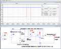
Not with the circuits in post #11. There is no capacitive divider! It is just a unity gain buffer and its output has a capacitor to ground (surprised it is still stable) and a bootstrap capacitor to the input. The output is 3.3V because the op-amp is powered from 3.3V and it is in clipping, because its input is at 4.4V
If both divider capacitors are the same physical size, and you assume 10GΩ of pcb surface leakage across each, within a minute the voltage on the inverting input of the op-amp will be half the battery voltage. If the actual surface resistance varies due to contamination, then it could be anywhere between 0V and full battery voltage.
I run the single 250 ns ADC battery voltage measurement each hour. When I unplug and plug again the development board (ATSAMR34- Xplained, without Op Amp) to USB port before each meaurement I am getting pretty steady right results. When I keep the board plugged the measured voltage decay. First picture Vbat 4.V and two other pictures Vbat 3.3V.
That’s because capacitive dividers don’t work with DC. @MrSalts said that in post#2, and many people have suggested alternative schemes.
If you return to the capacitive divider you return to a circuit that doesn't work. Of course, you can use SPICE to make it look as though it might work, but SPICE uses perfect components, with no leakage resistance.
Put 10GΩ across each of your capacitors and run it again.
I have just added TI LMC6482 (without the C=0.1µF) to capacitor voltage divider and I am getting rock steady ADC values without any problem. For 4.12Vbat 214 (0xD6) and for 3.3Vbat 162 (0xA2). ADC 8-bit resolution, Vref 3.3V and sampling time 250ns.
 Facebook
 Google
 GitHub
 Linkedin