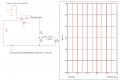
Battery measurement with Capacitor Voltage Divider & ADC

Juhahoo

Joined Jun 3, 2019
302
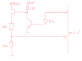
Typically batteries are measured by this type of circuit, it draw zero current during idle and draw current only when MOSFET conducts which is just enough to make the voltage measurement. Your GPS will draw significant amount of the current, one minute every hour, so resistor divider is a minor problem and will consume like <1mA x 1ms.
1631999124195.png
 
Last edited:

Thread Starter

Kevil

Joined Jun 28, 2020
224
I need to use the smallest packages for all components available i.e. 0201, DFN0606-3 etc. because of the micro PCB size (about 8 x 35 mm).
 

Ian0

Joined Aug 7, 2020
13,158
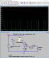
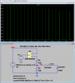
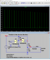
What am I doing wrong in the simulation?
You have made a source-follower. The voltage at the MOSFET source will be the voltage at the gate minus the Vgs(th) the gate threshold voltage. It will no longer depend on the voltage at the drain.
 

Ian0

Joined Aug 7, 2020
13,158
That variation may, or not be a problem. Pet collars are subject to wider temperatures as the pet ventures outside.
I hope 20 ppm/°C isn't a problem, because you'd not be able to use ordinary thick-film resistors, because they can be as much as 100 ppm/°C .
 

Ian0

Joined Aug 7, 2020
13,158
The MOSFET gate-source voltage is very temperature-dependent and varies considerably from one device to another.
 

Ian0

Joined Aug 7, 2020
13,158
That still suffers from exactly the same problems as the first version .
[edit] no it’s OK- I didn’t see it was P-channel. A P-channel MOSFET symbol would have been helpful! And it’s the same a @Juhahoo suggested in post #61
My circuit in post #58 will actually work and needs fewer components.
 
Last edited:

Ian0

Joined Aug 7, 2020
13,158
Surface resistivity for FR4 board is between 10^12Ω per square and 10^16Ω per square depending on environment. The distance between pads of any surface mount resistor is about the same as its width, so you should include a parasitic resistance of 10TΩ across each of your two "divider" capacitors. Then run the simulation, and think about a cat rambling through dewy grass and what the level of humidity on your pcb would be.

A quick calculation gives a time constant of about half and hour.
 
Last edited:

Thread Starter

Kevil

Joined Jun 28, 2020
224
"A quick calculation gives a time constant of about half and hour." That's fine I only need to measure the battery voltage every hour. I will get the same values with two parallel resistors 10T to C1 & C2.
 

Thread Starter

Kevil

Joined Jun 28, 2020
224
Typically batteries are measured by this type of circuit, it draw zero current during idle and draw current only when MOSFET conducts which is just enough to make the voltage measurement. Your GPS will draw significant amount of the current, one minute every hour, so resistor divider is a minor problem and will consume like <1mA x 1ms.
View attachment 248304
I simulated it and it draws 1.4/124µA on RVD. Looks good.
With NP-MOSFET's 2.6/120µA. I have a battery 550mAh.
 

Ian0

Joined Aug 7, 2020
13,158
"A quick calculation gives a time constant of about half and hour." That's fine I only need to measure the battery voltage every hour. I will get the same values with two parallel resistors 10T to C1 & C2.
You're not following. . . after about 3 time constants (90 minutes) the voltage on the A/D will be dependent ONLY on the two leakage resistances and NOT AT ALL on the capacitor values, REGARDLESS of how often you sample it.
@Juhahoo 's circuit (post #61) and mine (Post #57) will actually work.
 
Top