BAT54WS diode and temperature sensitivity

Thread Starter

PeterLauridsen

Joined Dec 11, 2024
3
Hello,

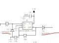
I am experiencing significant sensitivity to temperature changes with the BAT54WS diodes, which is affecting the measurement values due to environmental variations. I would appreciate any assistance in addressing this issue.

Additional hardware in use includes an ESP32 and an SCT013 AC current sensor.

Thank you in advance for your help.
 

Attachments

ronsimpson

Joined Oct 7, 2019
4,649
significant sensitivity to temperature changes with the BAT54WS diodes
What is happening with temperature?
What is to the left and right of the of the circuit?

D7: There are input protection diodes that are probably good to 10mA. I don't see a need for D7. The internal diodes will have about the same temp profile.
D4: Why? Probably this diode is the problem but without knowing what happens to the right I can't say.
1733959426102.png
 

Thread Starter

PeterLauridsen

Joined Dec 11, 2024
3
Hello,

The AC sensor on the left side can be found at the following link:
https://www.aliexpress.com/item/100...D4-9IbBT8r09eIXDw7P7eeNHE4VRzJ-hoCvWwQAvD_BwE

The right side is connected to IO32 and is used for analog reading. Below are the measurements recorded on IO32:

  • At +23°C, the voltage measured is 0.60V.
  • At -16°C, the voltage measured is 0.52V.
Let me know if you have any questions or need further details.
 

Attachments

Sensacell

Joined Jun 19, 2012
3,769
Why is there a diode there in the first place? What is the purpose?
It's a bad idea to place diodes in series with low level analog signals - unless you can tolerate the uncertainty of the diode's Vf.

If it's really necessary, include it within the feedback path of the opamp so the voltage drop is cancelled out.
 

ronsimpson

Joined Oct 7, 2019
4,649
D7 has little function and is not your temperature problem.
D4 should be removed. (shorted out).
At 100A the input should be about +/-1V rms. Depending on the 100A power factor, the Peak will be about 1.5V.
The op-amp will 2x the signal. The negative half will be 0V and the positive half will be about 3V.
1734014682489.png
 

Thread Starter

PeterLauridsen

Joined Dec 11, 2024
3
D7 has little function and is not your temperature problem.
D4 should be removed. (shorted out).
At 100A the input should be about +/-1V rms. Depending on the 100A power factor, the Peak will be about 1.5V.
The op-amp will 2x the signal. The negative half will be 0V and the positive half will be about 3V.
View attachment 337794
Thanks for the suggestion.

I will try these options and make another environmental test.
 

ronsimpson

Joined Oct 7, 2019
4,649
and make another environmental test.
Measure any voltage. Hit he diode with cold spray and measure. Then heat the diode with a soldering iron or hot air gun. Measure again. Because we think the problem is in that area, just heat or cool those parts.
Resistors should be OK.
OP-amp should be OK.
Diode is a problem.
 

sparky 1

Joined Nov 3, 2018
1,218
A capacitor on the output of the op amp will block the rectified DC from the feedback path.
DC will build up on the op amp output, a DC voltage near the supply voltage but is very small and varies with frequency.

Apply 20 mVpp input, replace R16 with 5.3K, place 50 Ohm to ground after the last diode to give you an impedance for comparison.
If you know your output impedance that will help, You can try a pi attenuator.
Pi Attenuator Calculator
 
Last edited:

MisterBill2

Joined Jan 23, 2018
27,193
The voltage to temperature plot shown in post #11 certainly looks like a good temperature sensor diode response. Like I said.

And how to evaluate a circuit when we are only shown a part of it?? And why expect us to follow a link to ????. I frequently do not waste time following links. It is up to the original posting person to copy from the link and show us the part.
I am guessing that the signal from the current transformer and burden resistor is a sine wave and the TS wants a DC value, along with protecting the input. Protection can be from a small series resistor and suitable clamp diodes. THAT is a standard scheme that serves very well. THEN, a "precision rectifier" circuit, such as shown in a number of opamp application guides, can provide an unfiltered output that can feed a suitable filter.
 
Top