Basic oscilloscope for newbie to troubleshoot a circuit

Thread Starter

Doctor_Ed

Joined Feb 10, 2022
72
I would suggest putting a small ceramic capacitor (maybe .05uF) across the right-hand diode feeding the optocoupler. That will filter out most high frequency noise coming from the power line, but will still allow 60Hz.
Well, that helped.

The pins of that diode projected invitingly on the underside of the board, so I tacked on a 0.04 µF. Now instead of the circuit tripping prematurely at about 40 sec, it trips at ~59 sec. Target of course is 60 sec. That is a big improvement.

I knew @Sensacell was right about a noisy AC source.

The counter section is almost for sure running OK.

I have an o-scope coming in a couple of days. With it, I should be able to refine the little network feeding the optocoupler. I think there is a good chance of getting the device to run at exactly 60 sec.

Thanks!
 
Here is a good place to learn about o-scopes:

https://www.tek.com/en/support/learning-center/oscilloscope

...particularly the PDF you can download here:

https://www.tek.com/en/documents/primer/oscilloscope-basics

Sparkfun has a pretty good tutorial:

https://learn.sparkfun.com/tutorials/how-to-use-an-oscilloscope/all

Also:

http://instrumentationlab.berkeley.edu/sites/default/files/Articles/Oscilloscope-Basics.pdf

You'll probably have to do some "translation" between what these guides detail, and the particulars of your scope; the biggest differences will be if you scope has the same functions, and how to access them.

If you do some googling and other machinations, you can find more than a few old books on using an oscilloscope, but most of them are geared to older analog CRT scopes, which usually didn't have the fancy mathematical tools and positionable "cursors" to do calculations and such with (you had to do all of that "by hand").
 

Thread Starter

Doctor_Ed

Joined Feb 10, 2022
72
Here is a good place to learn about o-scopes:

https://www.tek.com/en/support/learning-center/oscilloscope

...particularly the PDF you can download here:

https://www.tek.com/en/documents/primer/oscilloscope-basics

Sparkfun has a pretty good tutorial:

https://learn.sparkfun.com/tutorials/how-to-use-an-oscilloscope/all

Also:

http://instrumentationlab.berkeley.edu/sites/default/files/Articles/Oscilloscope-Basics.pdf

You'll probably have to do some "translation" between what these guides detail, and the particulars of your scope; the biggest differences will be if you scope has the same functions, and how to access them.

If you do some googling and other machinations, you can find more than a few old books on using an oscilloscope, but most of them are geared to older analog CRT scopes, which usually didn't have the fancy mathematical tools and positionable "cursors" to do calculations and such with (you had to do all of that "by hand").
Thank you for the links! Useful.

I also found some tutorials and YouTubes before I ordered the scope, so I think I'll be good. :)
 

Thread Starter

Doctor_Ed

Joined Feb 10, 2022
72
I don't have my scope yet, but I have made progress.

With the capacitor in place per @rick.curl 's suggestion, the device performed rock steady but slightly fast. The diagnostic LED1 was running between 36 and 37 flashes/min instead of exactly 36, causing the minute pulse to arrive about 1 second early. That's pretty good but not good enough.

On a hunch, I disconnected the FET1 loop. Now it runs on time. There must be feedback happening from that section, giving me 36 extra pulses per minute - 3636 instead of 3600.

I'm not sure if the FET2 circuit might be doing the same. If so, I would be getting 3601 pulses per minute, and the clock will gain half a minute per day. Time will tell, as the saying goes.

I think I better figure out a way to dampen that feedback.

The scope arrives tomorrow.
 
Last edited:

eetech00

Joined Jun 8, 2013
4,709
What are M1 and M2? Would we need both? The load draws only around 24 mA.
The 5v MCU GPIO pins cannot directly connect to a 24vdc load, so the NMOS (M1) permits isolation of the 5v and 24v voltage sources. The PMOS (M2) is only needed if you want to drive the positive side of the Clock while leaving the negative side connected to ground. If the RR clock input generates a transient kickback, then a diode should be connected in parallel with the Clock. Also, a smaller (100ma) DC adapter could be used.
 

Thread Starter

Doctor_Ed

Joined Feb 10, 2022
72
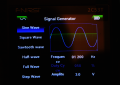
I have the scope now. It's the Fnirsi 2C53T. The multimeter and signal generator functions work fine. The oscilloscope part is a different story. After some diddling, it wouldn't display a sine wave from its own signal generator. Did a factory reset, and now it does show a sine wave. Low frequencies show the correct frequency, but higher frequencies show 2x or 3x the actual.

I would expect a 1200 Hz signal to show as 1200 Hz in the scope, but instead it shows as 3.58 KHz. This is trickier than I thought.
 

MrChips

Joined Oct 2, 2009
34,954
I have the scope now. It's the Fnirsi 2C53T. The multimeter and signal generator functions work fine. The oscilloscope part is a different story. After some diddling, it wouldn't display a sine wave from its own signal generator. Did a factory reset, and now it does show a sine wave. Low frequencies show the correct frequency, but higher frequencies show 2x or 3x the actual.

I would expect a 1200 Hz signal to show as 1200 Hz in the scope, but instead it shows as 3.58 KHz. This is trickier than I thought.
Show us a photo of the screen when it shows a 1200 Hz input as 3.58 kHz.
 

MrChips

Joined Oct 2, 2009
34,954
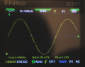
Ok. Thanks for the photos. Here is the basic calculation.

1200 Hz sine wave has a period of 1/1200 s = 833 μs
2400 Hz sine wave has a period of 1/2400 s = 417 μs

The oscilloscope is showing H=100 μs
This means that the horizontal sweep rate is 100 μs per division. (I see 12 divisions across the screen.)

On the oscilloscope screen, I see one complete sine wave cycle spans for about 8.3 divisions.
8.3 x 100 μs = 830 μs. This matches the 1200 Hz sine wave.

Trust what the waveform is telling you. Don't trust the digital frequency readout. The oscilloscope is very likely picking up noise and doing double counting.

In the case of it showing 3.58 kHz, it is triple counting. The oscilloscope is doing what your timer circuit is doing when there is noise in the signal.
You can experiment by putting a small capacitor (about 0.1 μF) across the leads of the oscilloscope and see if this filters out some of the noise.
 

Thread Starter

Doctor_Ed

Joined Feb 10, 2022
72
Ok. Thanks for the photos. Here is the basic calculation.

1200 Hz sine wave has a period of 1/1200 s = 833 μs
2400 Hz sine wave has a period of 1/2400 s = 417 μs

The oscilloscope is showing H=100 μs
This means that the horizontal sweep rate is 100 μs per division. (I see 12 divisions across the screen.)

On the oscilloscope screen, I see one complete sine wave cycle spans for about 8.3 divisions.
8.3 x 100 μs = 830 μs. This matches the 1200 Hz sine wave.

Trust what the waveform is telling you. Don't trust the digital frequency readout. The oscilloscope is very likely picking up noise and doing double counting.

In the case of it showing 3.58 kHz, it is triple counting. The oscilloscope is doing what your timer circuit is doing when there is noise in the signal.
You can experiment by putting as small capacitor (about 0.1 μF) across the leads of the oscilloscope and see if this filters out some of the noise.
Thanks a lot for your interpretation. I had no idea that one has to interpret (mistrust) the reported frequency. Indeed it was roughly doubling and tripling the frequencies.

Also I'm surprised at the noise, as this was a direct connection to its own signal generator.

In another case, I was checking the output of a commercial clock driver that runs off a crystal, powered by one AA battery. From observation, I know it generates a pulse every second. It reverses (turns 180 deg) a small magnet that drives the mechanism. So the frequency is 0.5 Hz. I was interested in knowing the wave form and the voltage. Just the task for a scope, right? The 2C53T produced a schmozzle, reporting KHz frequencies at times, and low Hz at other times, basically random stuff.

I would be able to help it if I could tell the scope what the frequency was, but I guess that is impossible.

I'm just an o-scope beginner and doing really basic things with it for now, and running into these problems. A bit surprising.
 

MrChips

Joined Oct 2, 2009
34,954
That is the problem when you place blind faith in high-tech tools, such as AI, for example.
The oscilloscope can only measure what it sees. If there is noise in the signal, we don't know how well the instrument performs in a noisy environment. Well, now we know how this particular oscilloscope performs. Don't necessarily blame the oscilloscope. Every instrument has its limitations. Clean up the signal and you might get better results.
 

Thread Starter

Doctor_Ed

Joined Feb 10, 2022
72
Bing Videos Hopefully for your scope.
You will find your scope very useful.
If the noise problem persists, build a simple two transistor multivibrator to explore.
Multivibrators | PDF Good luck..........
Thank you. It's almost impossible for an expert to explain to a novice how to operate a complex device. The only way is to have the learner present so they can interrupt. If I had been there in person, I would have stopped the presenter as soon as he said "DSO". Nobody knows what that means except for an expert. But experts don't know that.

We learners can still figure out how to operate things by reading the manual, following several sources, and experimenting. And googling terms like DSO. :)

I've pretty well figured this thing out, but am now running into unexpected limitations of the device.
 
Last edited:

MrChips

Joined Oct 2, 2009
34,954
Thank you. It's almost impossible for an expert to explain to a novice how to operate a complex device. The only way is to have the learner present so they can interrupt. If I had been there in person, I would have stopped the presenter as soon as he said "DSO". Nobody knows what that means except for an expert. But experts don't know that.

We learners can still figure out how to operate things by reading the manual, following several sources, and experimenting. And googling terms like DSO. :)
Oh, we have a thread for that:

https://forum.allaboutcircuits.com/...-acronyms-and-synonyms-in-electronics.194725/

(sorry, no DSO listed because we assume that everyone should know that one.)
 

Homebrew1964

Joined Nov 22, 2024
265
Oh i just read the entire thread and see you have a scope now, i bought one of those Fnirsi 2c53t's 3 days ago, havn't had a chance to play with it yet though.
 

Thread Starter

Doctor_Ed

Joined Feb 10, 2022
72
So I attempted to read the signal across diode D2 with the 2C53T scope. It was not easy. Once out of maybe 20 tries it succeeded. Frequency was reported as 60 and voltage p-p was 1.08. The scope keeps looking for kHz signals and won't latch on to the low frequency. Is there a setting to help this?

Also I have no idea how one would look for noise in this signal. Seems to me I'd need to record many cycles and closely inspect the trace. It's a rhetorical issue as the clock is running well now.

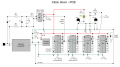
Here is the most recent circuit diagram of the clock driver.

1771466181308.png
 

skstrobel

Joined Nov 29, 2023
29
Quit looking at the frequency reported by the frequency counter function of your scope. As you know, it isn't giving you useful information. FWIW, that doesn't mean it is broken; there might be noise on the signal that it is correctly counting. The design of a general purpose tool like an oscilloscope involves tradeoffs (noise rejection versus frequency range and sensitivity) and those choices aren't giving you useful results. You might be able to overcome that with a capacitor across the leads to filter some noise, but you should still sanity check what it says.

What I'm suggesting is to use the method MrChips explained. When we had only analog oscilloscopes, it was the only way. Just count the number of horizontal divisions per wave (8.3), look at the time represented by each division (H=100 μs from the top of the screen), and do the math (1/(8.3*100uS)) = 1204.8 Hz. Your scope seems to work perfectly fine for that.
 
Top