Basic oscilloscope for newbie to troubleshoot a circuit

MrChips

Joined Oct 2, 2009
34,947
For starters, put a 0.1 μF ceramic disc capacitor between pins 8 and 16 of each one of the four IC counter chips, as close as possible to the actual IC pins. You can install them on the solder side of the board if that is easier to keep the legs of the capacitor as short as possible.
 

Thread Starter

Doctor_Ed

Joined Feb 10, 2022
72
For starters, put a 0.1 μF ceramic disc capacitor between pins 8 and 16 of each one of the four IC counter chips, as close as possible to the actual IC pins. You can install them on the solder side of the board if that is easier to keep the legs of the capacitor as short as possible.
Okay, thanks. I will have to acquire those.

And a correction on those resistors marked as 4700 - they are 15KΩ.
 
Last edited:

Sensacell

Joined Jun 19, 2012
3,786
What you will find is the edges of the pulses from your zero-crossing detector are noisy.
This is a common problem that leads to multiple counts per cycle. A good ZXD has a low-pass filter section that cleans up the very nasty noisy mains signal.

You might try this- it's a great little circuit I use all the time.
 

Attachments

Thread Starter

Doctor_Ed

Joined Feb 10, 2022
72
What you will find is the edges of the pulses from your zero-crossing detector are noisy.
This is a common problem that leads to multiple counts per cycle. A good ZXD has a low-pass filter section that cleans up the very nasty noisy mains signal.

You might try this- it's a great little circuit I use all the time.
Thanks. I'm wondering if noise is also getting fed back from the counters. LED1 speeds up when the load is energized. All very strange as the breadboard worked well.
 

BobTPH

Joined Jun 5, 2013
11,570
Did you mean this one? The link is not specific.

View attachment 363166
“Battery operated” is the operational phrase. Any battery operated scope avoids a problem with connecting the scope ground to the circuit. With a line powered scope, you cannot connect the ground lead to any part of the circuit except the AC ground. A battery operated scope allows you to safely connect it anywhere in the circuit under test.
 

Futurist

Joined Apr 8, 2025
832
The green leads are connected to 120V AC.

No worries. The final project will be safe.

View attachment 363205
I simply have to disapprove strongly, only if it was absolutely necessary would a prudent person expose that kind of danger as you are doing.

Having two terminal bolts/nuts exposed like that is asking for trouble. I (regrettably) never worked professionally in electronics but it was my hobby as a teen and I later studied two years full time on electronics, radio, telecoms, marine radio, microprocessors, digital design, electrical installations and safety was emphasized day in and day out in the engineering college I attended.

At the very least use an isolation (1:1 ratio) transformer.

With all due respect what you are doing is simply very bad practice. workshop/lab safety is absolutely to be respected.

Although the risk might seem low, might feel rather low, you want it as low as humanly possible all the time, anything less can (and does) kill people.

I did dumb stuff as a teen and even in college, and got a serious talking to by any lecturer who saw that, they would not tolerate it and I learned a lot from them in that respect.
 
Last edited:

Thread Starter

Doctor_Ed

Joined Feb 10, 2022
72
I simply have to disapprove strongly, only if it was absolutely necessary would a prudent person expose that kind of danger as you are doing.

Having two terminal bolts/nuts exposed like that is asking for trouble. I (regrettably) never worked professionally in electronics but it was my hobby as a teen and I later studied two years full time on electronics, radio, telecoms, marine radio, microprocessors, digital design, electrical installations and safety was emphasized day in and day out in the engineering college I attended.

At the very least use an isolation (1:1 ratio) transformer.

With all due respect what you are doing is simply very bad practice. workshop/lab safety is absolutely to be respected.

Although the risk might seem low, might feel rather low, you want it as low as humanly possible all the time, anything less can (and does) kill people.

I did dumb stuff as a teen and even in college, and got a serious talking to by any lecturer who saw that, they would not tolerate it and I learned a lot from them in that respect.
Thank you, I appreciate what you are saying. My electronics experience (such as it is) goes back many years when practices were very different. Mains connections were left exposed; nobody worried about big capacitors (they were discharged on metal strips to see the spark); old loudspeakers were plugged into the mains so they could die in glory. Times and standards are very different now. So thanks for the talking to. I will go shopping for an isolation transformer.
 

Thread Starter

Doctor_Ed

Joined Feb 10, 2022
72
I'm finding out the circuitry around the optocoupler is very nervous. Touching a part of it with a loose wire causes LED1 to change speed. Increasing or decreasing the value of one of the resistors drastically changes the flashing rate. There might be proximity effects happening. Maybe I need shielding or coax wiring.

I'm over my head reading the data sheet. "Forward Input Current" - that must be the photodiode current. Do they mean instantaneous peak current? If so, I think my circuit is in the right range.

Hanging a probe from a scope on the optocoupler circuitry will change the signal I'm trying to measure.

The counter section is probably working properly, but I suspect the opto part isn't.
 

Futurist

Joined Apr 8, 2025
832
Thank you, I appreciate what you are saying. My electronics experience (such as it is) goes back many years when practices were very different. Mains connections were left exposed; nobody worried about big capacitors (they were discharged on metal strips to see the spark); old loudspeakers were plugged into the mains so they could die in glory. Times and standards are very different now. So thanks for the talking to. I will go shopping for an isolation transformer.
Can you (or anyone here) explain why the device needs to connect to the AC supply other then for driving the 24v DC supply? What's the opto isolator for? Surely its worth eliminating this dependency then you can simply drive and test using a bench supply set to 24v?

Perhaps its to gen a 60Hz source? if thats the case then at least use a small isolation transformer perhaps giving you 24v AC, and derive the 60 Hz from that and generate 24v DC from that 24v AC? then the AC mains is used ONLY to supply the transformer? This way your entire circuit is powered from 24v AC, a much safer setup, you could lose the opto isolator then as well.

Seriously (I will defer to the experts here though) eliminating this reliance on 120v line AC, is the biggest problem in this setup, and should be addressed before anything else.

Look at this, you get 24v AC and isolation! (I apologize for the ugly URL, but the website's editor behaves poorly when using a tablet, many other sites don't misbehave like this).

https://www.amazon.com/Transformer-Thermostat-Competible-Versions-Honeywell/dp/B07DJ7RHS5/ref=sr_1_8?crid=1EELIXFBRCUMX&dib=eyJ2IjoiMSJ9.5Tx2X1G62plNw1BgcPfXjODE7hDO7NSHNza_nwIO_H8E0X_76CZCysG3Imy0ykBKU-L97kO9IevV0tJwgwX2Ctmd5lsPlEunGzOUrGCJi2weeZE9DUU9v-bgK9Gs46pU9aIxQVXwCgsUHvx57Fs0Ogg6BaOxkAPEGyQchrdmMjLEm3UiQlbSypjI4wmpP8I49cBGzUQOY_CeTWdbj4epYmN81cRMIUiInCJ7xsU_66I.67L7gwN4gDbe2zz8f1GQYq33UGY2i_o3ecfpfj_QpMM&dib_tag=se&keywords=transformer+120v+to+24v&qid=1770562117&sprefix=transformer+120v+,aps,564&sr=8-8
 
Last edited:

Thread Starter

Doctor_Ed

Joined Feb 10, 2022
72
Can you (or anyone here) explain why the device needs to connect to the AC supply other then for driving the 24v DC supply? What's the opto isolator for? Surely its worth eliminating this dependency then you can simply drive and test using a bench supply set to 24v?

Perhaps its to gen a 60Hz source? if thats the case then at least use a small isolation transformer perhaps giving you 24v AC, and derive the 60 Hz from that and generate 24v DC from that 24v AC? then the AC mains is used ONLY to supply the transformer? This way your entire circuit is powered from 24v AC, a much safer setup, you could lose the opto isolator then as well.

Seriously (I will defer to the experts here though) eliminating this reliance on 120v line AC, is the biggest problem in this setup, and should be addressed before anything else.

Look at this, you get 24v AC and isolation! (I apologize for the ugly URL, but the website's editor behaves poorly when using a tablet, many other sites don't misbehave like this).

https://www.amazon.com/Transformer-Thermostat-Competible-Versions-Honeywell/dp/B07DJ7RHS5/ref=sr_1_8?crid=1EELIXFBRCUMX&dib=eyJ2IjoiMSJ9.5Tx2X1G62plNw1BgcPfXjODE7hDO7NSHNza_nwIO_H8E0X_76CZCysG3Imy0ykBKU-L97kO9IevV0tJwgwX2Ctmd5lsPlEunGzOUrGCJi2weeZE9DUU9v-bgK9Gs46pU9aIxQVXwCgsUHvx57Fs0Ogg6BaOxkAPEGyQchrdmMjLEm3UiQlbSypjI4wmpP8I49cBGzUQOY_CeTWdbj4epYmN81cRMIUiInCJ7xsU_66I.67L7gwN4gDbe2zz8f1GQYq33UGY2i_o3ecfpfj_QpMM&dib_tag=se&keywords=transformer+120v+to+24v&qid=1770562117&sprefix=transformer+120v+,aps,564&sr=8-8
I don't see a need to change the existing 24 v power supply. It works fine. But replacing the opto section with a little transformer might solve some problems. (... or just a dropping resistor??)
 
Last edited:

Futurist

Joined Apr 8, 2025
832
I don't see a need to change the existing 24 v power supply. It works fine. But replacing the opto section with a little transformer might solve some problems. (... or just a dropping resistor??)
Of course you need the 24v DC that's not the issue. But you don't need 120v AC to generate the 60 Hz signal, 24v AC isolated is much safer. I think it is frankly bad design to use the 120v AC line as you are doing, just power the thing from 24v AC (from which it is trivial to generate 24v DC).

1770569653845.png1770569721163.png


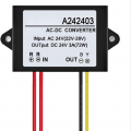
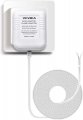
Total of 30 bucks at Amazon, no doubt cheaper if you look around. This isn't the only way to do it, but these can be used in your circuit with vert little change I imagine. I'm assuming that stepdown transformer is 100% isolated but even if not it is much safer than what you are doing.
 
Last edited:

Thread Starter

Doctor_Ed

Joined Feb 10, 2022
72
@Futurist , OK, I see where you are going with this. Wall-wart to get me 24VAC, then safely into my driver module. Yes, that would be better.

Before I build it, I would want to know that the signal is behaving.
 

MrChips

Joined Oct 2, 2009
34,947
You can pick up power adapters from your local second hand store for less than $5.
Last week I bought a bag of 4 adapters, random outputs, for $4.99.
 

Thread Starter

Doctor_Ed

Joined Feb 10, 2022
72
You can pick up power adapters from your local second hand store for less than $5.
I have a dozen in a bin. But the output might be filtered.

Edit: Yes, I opened one up. Full wave rectification and lots of filtering.
 
Last edited:

MisterBill2

Joined Jan 23, 2018
27,725
What is the intended purpose of that 150 PF capacitor from the mains side to the low voltage common?? That totally does not seem right. It might even be the problem.
 

Thread Starter

Doctor_Ed

Joined Feb 10, 2022
72
What is the intended purpose of that 150 PF capacitor from the mains side to the low voltage common?? That totally does not seem right. It might even be the problem.
I got the idea for that capacitor from an optocoupler circuit online. It helped the breadboard circuit, which ran well with it. I don't understand its function, though. When I saw your post, I ran downstairs to the shop and removed that cap and tested the device. It caused it to run even faster than before.

The gate of FET1 is connected to pin 3 of the second counter. That is a convenient diagnostic point. It should flash at 0.6 Hz, but it is more like 0.9 Hz. I decided to move the connection to pin 3 of the first counter. The frequency should be 10x higher there, 6 Hz. What I observed was chaotic flickering. I don't need an oscilloscope to see that the signal is very bad. At times it's dark for as long as a second, followed by a burst of rapid flashes.

I have resoldered some of the pins of the first counter, and a couple of other spots too, in the hopes of remedying an invisible fault, but no difference so far.

Thanks for your suggestion.
 

Sensacell

Joined Jun 19, 2012
3,786
Redesign your Z-Xing detector! it's a bad design- no low-pass filtering!!
The HCPL2201 can pass 5Mbaud signals! -and you are looking for 60 Hz.

The AC mains are a nasty sewer of noise, you need to chop-off all the higher frequencies and get ONLY the 60 Hz.
If you had a scope, you would probably see multiple edges clustered together at every crossing, causing the fast counting.
 
Last edited:
Top