Basic Connection Problem - Yoctowatt

Thread Starter

Sijia Wu

Joined Jul 22, 2015
23
Hi,

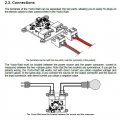
I am using a YoctoWatt to measure voltage and current, and I am having problems with the connection. The screenshot from the user manual of YoctoWatt is all the information needed to build and test the connection, I think

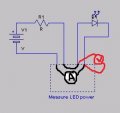
I built a simple testing circuit but it's not working for me. When the YoctoWatt isn't connected, I get 1.2V over the resistor and 1.7V over the LED. But when I connect the YoctoWatt, using a multimeter I get 0V for both; the LED isn't on.

Wondering what the problem is. Am I connecting it wrong?

Thanks in advance!
 

Attachments

MikeML

Joined Oct 2, 2009
5,444
The implication is that this device is for measuring power consumed by 120Vac or 240Vac appliances. Likely does not have sufficient sensitivity to work with a voltage that low...
 

Thread Starter

Sijia Wu

Joined Jul 22, 2015
23
So there isn't any problem with the connection itself?

The low voltage supply could be why. But I got scared because the last time I worked with 48V I almost got electricuted...
 

MikeML

Joined Oct 2, 2009
5,444
I'm trying to measure power into the LED
Then the LED current-limiting resistor and battery must be upstream of the device. Only the LED is downstream. It internally monitors the voltage across the LED and the current through the sensor.

The polarity of the LED has to be such that the connection through the device connects LED cathode to the negative pole of the battery.
 

MikeML

Joined Oct 2, 2009
5,444
I tried both (pictures attached); LED still wouldn't light up. If it's because of the low voltage supply that the measurements don't yet work, at least it should act like a low-resistance ammeter and let current flow through the LED?
Leaving the battery side untouched, did you try both possible orientations of the LED?
 

Thread Starter

Sijia Wu

Joined Jul 22, 2015
23
Leaving the battery side untouched, did you try both possible orientations of the LED?
Yeah I did. When I pulled all the Yoctopuce wires out and just connect the battery and LED/resistor, it lit up and I marked the right orientation.
 

MikeML

Joined Oct 2, 2009
5,444
Since I don't have a manual, and you do, maybe you could do a little reading and check to see if that beast has a current shunt built into it or not!
 

Thread Starter

Sijia Wu

Joined Jul 22, 2015
23
Since I don't have a manual, and you do, maybe you could do a little reading and check to see if that beast has a current shunt built into it or not!
In the manual http://www.yoctopuce.com/EN/products/yocto-watt/doc/YWATTMK1.usermanual.html,
search of "shunt" only returns "To convert current into a measurable voltage, the Yocto-Watt uses a large metal shunt (a resistance of 0,01 Ohm), located between the two connectors. As the current increases, the temperature of the shunt rises as well. The shunt is designed to be self-cooled by convective heat transfer. At 16 A, the shunt temperature on the upper side may rise above 120°C. This is the normal way for this component to dissipate heat. However, for the convective heat transfer to work properly with high amperage, you should make sure that the Yocto-Watt is kept in its upright position. If you use the device in an enclosure, make sure the enclosure is properly vented, to ensure proper operation of the device and prevent fire hazards."

Is that what it is?
 

MikeML

Joined Oct 2, 2009
5,444
That is what I expected. Take an Ohmmeter, and use it to identify which pair of screw terminals has a very high resistance, and which looks like a dead short.

The high resistance ones are used to measure V and the ones with the low resistance ones have the current flowing through them to measure the current. The device calculates power by multiplying the two readings. If either is mis-connected, the product will be zero...
 
Last edited:

Thread Starter

Sijia Wu

Joined Jul 22, 2015
23
That is what I expected. Take an Ohmmeter, and use it to identify which pair of screw terminals has a very high resistance, and which looks like a dead short.

The high resistance ones are used to measure V and the ones with the low resistance ones have the current flowing through them to measure the current. The device calculates power by multiplying the two readings. If either is mis-connected, the product will be zero...
These are the results...what do they say, and how does that change the connection?
 

Attachments

Thread Starter

Sijia Wu

Joined Jul 22, 2015
23
That is what I expected. Take an Ohmmeter, and use it to identify which pair of screw terminals has a very high resistance, and which looks like a dead short.

The high resistance ones are used to measure V and the ones with the low resistance ones have the current flowing through them to measure the current. The device calculates power by multiplying the two readings. If either is mis-connected, the product will be zero...
This connection seems to be following the rules - low resistance ones let the current pass, and high resistance ones are measuring the voltage.
 

Attachments

Top