Bascule bridge for dummies

Thread Starter

Cbrady01417

Joined Mar 29, 2019
7
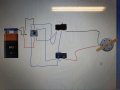
I need to make a simple model of a bascule bridge. The design must have 2 limit switches that stops the motor at the top and then reverses when I switch a dpdt switch. Followed by the other limit switch ending the cycle. ( in an ideal world I'd prefer if it automatically reversed but this may be a head of my current skill set)

I'm new to electronics and wondering would anyone have any ideas of how to do this with out using relays or arduino etc... a wiring diagram would be helpful or pointers of any kind
 

Thread Starter

Cbrady01417

Joined Mar 29, 2019
7
Albert... top man for replying to my first ever post...

From the above diagram... still confused (hence the dummies part)

How does that all wire up?

Apologies for sounding thick
 

Thread Starter

Cbrady01417

Joined Mar 29, 2019
7
I only understand certain parts...

To me I can see a motor, power supply and at a guess 2 things that look like diodes or are they limit switches on either side!

I'm likely to be very wrong
 

AlbertHall

Joined Jun 4, 2014
12,625
The two things with arrow heads are indeed diodes and the things they connected across are the limit switches.
Do you know how much the motor needs then I can suggest a diode type?
 

djsfantasi

Joined Apr 11, 2010
9,237
Diodes have a band at the end the arrow points.

So you would connect two diodes to both ends of a normally open limit switch. Do this twice.

Then take one of the assemblies, and wire the end away from the diode band to the motor.

Repeat for the other assembly and the other motor connection/wire. Both wires connect to the end which the diode end with the band connects.

Finally, wire the other end of the switches to a “reversing switch” common contacts. You need a DPDT switch.

Then, wire both wires from your power supply to one end of this switch. Finally, attach two short wires to this end of the switch, cross them and connect them to the other end of the switch. This will reverse polarity. Crossing the wires is what does this.
 

Thread Starter

Cbrady01417

Joined Mar 29, 2019
7
HI lads...

Again thanks for all your help... I will give it a ago in school on Monday and forward on my results and likely a cry for help if I can't figure it out...
 

Thread Starter

Cbrady01417

Joined Mar 29, 2019
7
Ok...

I have connected this up without diodes. The circuit works apart from the fact that when the bridge is fully raised and hitting the first limit switch it will not reverse when I throw the toggle across to reverse it.

Where in this set up would I put diodes to stop this happening.
 

Attachments

AlbertHall

Joined Jun 4, 2014
12,625
The diodes should be as below but the directions may need to be reversed as it depends on which motor polarity opens which limit switch - but they should both be changed if needed, not just one.

[EDIT: Sorry I got the diodes wrong. One of them -either one - should be reversed :oops:]

The wire marked by the red arrow should not be needed and should be removed. If it is needed then you have the wrong connections on the microswitches. The wires should connect to the COM and NC terminals.20190401_104234.jpg
 
Top