Facebook
 Google
 GitHub
 Linkedin

What solutions exist for solving the problem of when an IC's output will be back-driven from another IC's output when both are driving the same input of a 3rd IC?
For example: I have a counter, and I want to drive the clock pin either with an oscillator, or manually with the output from a button.
I can use an AND gate or 4066 switch etc to disable the input from the oscillator but then I have the output of that IC connected to the output of my IC handling the buttons, both connected to the clock pin.
So, when I hit the button and this sends a pulse, that current will be sent into the output of the gate used for switching the oscillator signal, and vice versa, when the clock is enabled and running, and the button is not being used.
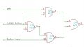
As I can see it, there are several options. First is an OR gate. I think this is the logical way, problem is, an extra gate.
Second idea I came up with was using two diodes, but I wonder if the voltage drop may be an issue.
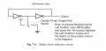
Third (which I saw in a book) hinted at the possibility of using high value (eg: 10k+) resistors in series with the outputs to limit current, but the information was not well detailed, and I do not know if it would be OK in all cases.
Does anyone use this concept in their own designs? Are resistors suitable? Would diodes work?
Are there any other options?
For example: I have a counter, and I want to drive the clock pin either with an oscillator, or manually with the output from a button.
I can use an AND gate or 4066 switch etc to disable the input from the oscillator but then I have the output of that IC connected to the output of my IC handling the buttons, both connected to the clock pin.
So, when I hit the button and this sends a pulse, that current will be sent into the output of the gate used for switching the oscillator signal, and vice versa, when the clock is enabled and running, and the button is not being used.
As I can see it, there are several options. First is an OR gate. I think this is the logical way, problem is, an extra gate.
Second idea I came up with was using two diodes, but I wonder if the voltage drop may be an issue.
Third (which I saw in a book) hinted at the possibility of using high value (eg: 10k+) resistors in series with the outputs to limit current, but the information was not well detailed, and I do not know if it would be OK in all cases.
Does anyone use this concept in their own designs? Are resistors suitable? Would diodes work?
Are there any other options?



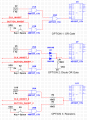
 I'm not new to drawing them up, only new to designing circuits myself.