Autism electronic sensory box

djsfantasi

Joined Apr 11, 2010
9,237
Ok Folks

Finally! we have a finished sensory box

Now for all of you lovely smart folks to show me how to wire this bad boy!!!

I have attached all the pics I hope will be enough info for your diagrams in point to point drawings,

***PLEASE NOTE I DO NOT HAVE ENOUGH COMMON SENSE TO KNOW HOW TO WIRE MULTIPLE CABLES OFF ONE CABLE***

All LEDs are standard 5mm and all + connections are to the left, the battery pack is a standard 4 way AA pack

I would prefer to solder requested resistors to a cable first and then to the led probes if at all possible

I.e Red cable to the + connection and White to the - connections

If possible can you folks also show me how to wire the traffic light lamps connected to the rotary switch, they appear to have 1 long short and 1 short leg.

Also, if you could please be so kind as to let me know the size of resistor I require for each LED, I realise that the colour of each LED requires a different resistor.

On top of this, can you please also show me via point to point diagram when pins on each switch connects to red or white wires
(or whatever colour of cables you suggest)

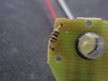
The push on - push off led light on the left hand bottom corner of the lid was orginally powered by 3 x 1.5v AAA batterys, however as you can see I have done away with those, and soldered some longer leads to the + and - connections on the pcb, I note that the existing pcb from that light has a tiny wee resistor (i'm guessing to reduce the voltage for the led?)

Guys, once again many thanks for all of your fantastic and informative help, I really am truly sorry for so many questions and my stupidy to date.

I do not know how to wire in series or paralell hence, the need for point to point and coloured cable drawings.

In relation to the 3 traffic lights for the rotary switch, I honestly do not know if they are lamps or leds?

I had a look at the writing on the side of them and they dont mention part numbers or anything like that, they just state the make of them

I honestly hope that all of the above wording and attached pics are enough for you smart folks to figure out and again I am very sorry for any silly statements on my part.

I just want to get this finished for my young son, all that is stopping me now is the actual wiring of said project

:)

Best Regards

Glenn.
You noted that all LED positive connections are to the left. Just to be clear, to the left as viewed from the back, correct?

The rocker switch is used... how?

The push on/ push off light probably has a resistor to reduce the current. Does it have colored stripes on it and can you tell what they are?

Regards the three indicators near the rotary switch, do you have a 330 ohm resistor available? An experiment using the battery pack, the resistor and one indicator might be necessary. They may be lamps, as the terminal types are used for lamps. But you say they have one shirt and one long leg, which is consistent with an LED. We need to confirm which.

And unfortunately, I cannot make out long distance, how the rotary switch should be wired. Do you have a multimeter? (That would also help with identifying the traffic lights).

I may suggest using bare copper wire for all of the negative connections. It’s available at home supply stores or a neighborhood hardware store.
 

Thread Starter

Deputyduke

Joined Apr 22, 2019
32
You noted that all LED positive connections are to the left. Just to be clear, to the left as viewed from the back, correct?

The rocker switch is used... how?

The push on/ push off light probably has a resistor to reduce the current. Does it have colored stripes on it and can you tell what they are?

Regards the three indicators near the rotary switch, do you have a 330 ohm resistor available? An experiment using the battery pack, the resistor and one indicator might be necessary. They may be lamps, as the terminal types are used for lamps. But you say they have one shirt and one long leg, which is consistent with an LED. We need to confirm which.

And unfortunately, I cannot make out long distance, how the rotary switch should be wired. Do you have a multimeter? (That would also help with identifying the traffic lights).

I may suggest using bare copper wire for all of the negative connections. It’s available at home supply stores or a neighborhood hardware store.

Thanks matey, please see attached photo of resistor on the pcb of the push on/off light it was originally powered by 3 x 1.5v AAA batteries i have removed the battery casing and extended the red and white + and - leads as you can see in the picture of the underside of the lid.

I do have a digital multimeter if you cN let me know how to do the required tests that you need.

The rocker switch i would like to be a master power switch to turn the whole box off should my son go to sleep for example and leave say the toggle switches on.

Ive just realised that on of the traffic lights will prob always be on as its a 3 way rotary switch Grrrrr.

Yes the leds all have the + leg to the left when looking straight at the lid from the front.
 

Attachments

Thread Starter

Deputyduke

Joined Apr 22, 2019
32
Here is a diagram.
As I do not know what your "Traffic Lights" are, that part is a bit of a guess.
In one of your other posts, the rotary switch had 3 banks all green. That would be better as I think the red bank will have the lamp on until it is operated. So if you can change the switch for the other one, that may be an idea.

Thank you sir, the battery pack is glued into place the three traffic lights are the only 3 ones i have they were given to me by a friend.

Wpuld we able to wire these so as the red one is always on like you say and then goes out as soon as the rotary is move to another positin to illuminate the next one?
View attachment 176721
Run one black wire around all the LEDS and just scrape a bit of insulation off at each point you need a connection if you do not want to join wires.

View attachment 176720
If you move the battery pack to the side near the switch, then the red wire from the battery will reach the switch.

All the resistors can be the same, and 470ohm will work. Lower it if you need more brightness. The calculated resistors mentioned for 20mA will be the minimum value you should go to. There is no reason to run the LEDs at 20mA. A lot less current will be ok, as long as they are bright enough. Try some resistors and see. Just do not go too low a value that will over stress the LEDs.
 

Thread Starter

Deputyduke

Joined Apr 22, 2019
32
I was also given a piece of breadboard and hook up solid wires of difgerent colours would that be easier to put all the wires into?

I can upload a pic of the breadboard if needed
 

dendad

Joined Feb 20, 2016
4,639
I was also given a piece of breadboard and hook up solid wires of difgerent colours would that be easier to put all the wires into?

I can upload a pic of the breadboard if needed
Breadboard is not good for final products, just for developing them. The wires will fall out when the box is dropped.
Joining the wires is easy. Just strip off some insulation at the ends, twist the wires together and solder it.
Please wear safety glasses when soldering and make sure to wash your hands well after.
 

Thread Starter

Deputyduke

Joined Apr 22, 2019
32
Breadboard is not good for final products, just for developing them. The wires will fall out when the box is dropped.
Joining the wires is easy. Just strip off some insulation at the ends, twist the wires together and solder it.
Please wear safety glasses when soldering and make sure to wash your hands well after.

Thsnk you i forgot to say i still have a 5mm led to add above the big centred black rocker switch
 

Thread Starter

Deputyduke

Joined Apr 22, 2019
32
Lads, I know this sounds really really stupid but I am struggling to follow even the basic point to pint wiring drawing!!!!

May I be really really cheeky and ask would any of you kind guys write me down the wiring in steps.

example

Step 1: Solder red lead to LED + then to battery + then to Switch + (Example)

Step 2: Solder Led - to Switch - etc........

I am getting very very frustrated, as my tiny brain seems to have hit a dead wall, all I need now is to wire this bloody box and give it to my wee son.

Thanks guys and I am sorry for being so annoying to you all

Glenn
 

djsfantasi

Joined Apr 11, 2010
9,237
Ok, I was almost done with most of a point to point wiring diagram

I say almost because I don’t know enough about your push-on/push-off led light. Nor do I have a clue about what the indicators (lights, leds, ...) are. Nor can I figure out your rotary switch.

The rotary switch may be the easiest. Find two connection points that have continuity (zero ohms on the multimeter). Then turn the switch and find two more points that are connected. One will be the same as the first test and that will be the common. Turn the switch to the third position and with one probe on the common position between the first two tests, find a third position with connectivity. Mark your closeup with these four positions identified and post it here.

It appears you have two power switches? One on the side and the rocker switch.

And what is this new led for? How will it operate?
 

Thread Starter

Deputyduke

Joined Apr 22, 2019
32
Thank you my good man

Here is a link to the push on battery operated light

https://www.diy.com/departments/dia...VB7LtCh235gWOEAYYASABEgLWnPD_BwE&gclsrc=aw.ds

it originally ran on 3 x 1.5v AAA batteries (4.5v power required in total), all i have done is taken away the battery compartment and extended the original + and - leads from the PCB to finally power from my new 6v battery pack in my sensory box.

I have also attached a couple of pictures of the markings on the sides of the rotary switch and the back connections if this helps
 

Thread Starter

Deputyduke

Joined Apr 22, 2019
32
I used the multi-meter on the rotary switch to check for continuity between the connections I hope this uploaded picture helpsCONTINUTY.jpg
 

Thread Starter

Deputyduke

Joined Apr 22, 2019
32
lid new leds.jpg lid new leds reverse.jpg Here is a picture of the 2 new red 5mm leds i have added to the big black rocker switch in the centre of the box.

Note:- The red master power on / off switch at the side of the box is to kill all power to it should my young son go to sleep and leave the switches powering the leds on

I also have postioned these 2 new 5mm red leds with the + leg facing to the left when looking at the lid straight on from the front so as they are in the same direction as the other leds on the lid
 

djsfantasi

Joined Apr 11, 2010
9,237
Anyone? Am I missing something here?

Deputy said (in post #62) that the big rocker was to turn off everything... and the side rocker apparently does the same thing.

Also, he said he was adding one red led. Now there are two. And I still don’t know how these LEDs are going to be used...

DeputyDuke, you have to be explicit in your descriptions and you have to stop changing the requirements. You need to carefully answer the questions asked. For example, I asked you to label 4 points on the rotary switch. I expected one to be labeled “common”. You labeled some with something about LEDs that wasn’t asked for... If you go back,besides common, label the rest A,B, & C, for the connection points that are switched.

Has anyone else figured out the rotary switch?

You can provide more information about the push-on/push-off light. Using your DMM, measure the resistance of the resistor in the light. To help, I’m expecting your answer to be an integer. In ohms. Nothing else will make sense to me. We need this because if you hook up 6V to that light, it will probably stop working.
 

dendad

Joined Feb 20, 2016
4,639
I notice you have pictures of a number of different backs of the rotary switch. You need to have all 3 segments the "NO" type, not the "NC" ones. The "NC" switches will have the LEDs on untill the switch is in that position, then it will go off.
 

Thread Starter

Deputyduke

Joined Apr 22, 2019
32
Lads i sense your frustration at my stupidity and for that i yet again am truly truly sorry.

All things set aside can we please start afresh.

This is the final design no further changes will be made i promise i also promise to carry out each instruction requested from me by you guys.

Can we please start the wiring process from the very very first beginning

I will ensure on my part to carry out each instruction 1 step at a time and every time i post in this great forum i will then ask for my next step instruction.

So may i please ask my first step for example the front left toggle switch which colour of cable do i need to solder from what pin on the switch to what size of resistor to what leg of the red 5mm led along the top of the box.

Or wherever else i can start with the kit i have to dste

Again i thank you for your patience with my small pea sized brain

Thank you all and again i really appreciate your patience in this whole matter.

I would seriously consider installing skype or another IM program if it is faster to you guys.

Regards

Glenn.
 
Top