Does “10 way AA Battery Holder” mean that it holds 10 AA batteries?
Way too much power. You only need 4 AA batteries for this project. Ten batteries would have to waste more than half of its capability and could damage the LEDs.
You will also need to obtain some resistors. It looks like you will need two different values. 1/8 or 1/4 watt resistors will be fine. Don’t worry now what that means. I mention the Watts because you will see it when you look for resistors to buy.
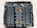
As I remember, all of the switches except for the toggles have two connections. The toggles have six. That’s ok, we won’t use four of them. I drew a picture showing you which two connections to wire to. In the case of the switches, it doesn’t matter where each wire connects.
In the case of the LEDs, it does matter which wire goes where. An LED has one long lead and one short lead. I mark which one to use on the diagram.
I show wires attached in the middle of another wire in several places. You can remove the insulation along a wire or just piece short pieces together. These joints need to be insulated. You can get some heat shrink tubing or use vinyl electrical tape.
I’ll attach the picture later. I just wanted to give you a heads up. AND please reply with the answer about the battery holder.
To use the battery holder, you would have to solder a new wire to the spring at the last used battery position. Warning, this may be difficult as those spring wires may not take the solder well. Make sure you identify if the soldered wire is positive or negative. Use the same color wire as the battery holder has for that end of the battery. You could also short out the unused positions, by soldering a wire from the last battery end to the last battery position.
You can solder 3-4 wires to an other wire. Its not difficult, but its not easy either. The increased mass of all those wires will take more heat for them to melt to solder. Note! The wires/connections should be heated and the solder melted onto them. Do NOT melt the solder and apply it with the gun to cold wires...
Your last comment makes me think. Most of the components you show look like they are for a heavy duty electrical installation. This project is a low voltage/ low current application. You only need 22g or 24g wire. Thicker wire will be more difficult to solder and its stiffness may break the joints to the switches and LEDs.
Im working on recommended resistors today. If you're curious, this is a good link to learn about LEDS.
OK, I've calculated the resistors that I recommend. It usually doesn't take this long, but life happens.
For the red, yellow and orange LEDs, use
400Ω, 1/8W resistors
For the blue and green LEDs, use
330Ω, 1/8W LEDs
I had another thought re: your battery pack. This might be easiest.
Get a penny and polish it. Drill a 1/16" hole on the edge. Insert a black wire into the hole and solder. Put the batteries into the pack making sure the first one is at the end with the positive or red lead. Insert the modified penny between the spring and contact of the last battery. Use this wire as the negative supply for your circuit.
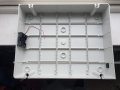
I started the drilling stage today ended up mounting 6 x 5mm LED holders along top of lid. I also got the first toggle switch mounted directly below 1st LED holder.
I will do some more drilling tomorrow.
To make life easier i presume i would be better juat going onto ebay and ordering a 4 cell or 6 cell AA holder?
I started the drilling stage today ended up mounting 6 x 5mm LED holders along top of lid. I also got the first toggle switch mounted directly below 1st LED holder.
I will do some more drilling tomorrow.
To make life easier i presume i would be better juat going onto ebay and ordering a 4 cell or 6 cell AA holder?View attachment 176123
Probably. But I wouldn’t get the 6 cell holder. The resistor values were calculated for a 6V supply - 4 AA cells. Six would require different resistors.
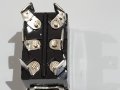
Here’s a picture from a recent project. I needed single pole single throw (SPST) switches. That a simple on/off switch. But I only had ones like some of your toggle switches. With six connections. That’s a double pole double throw (DPDT) Switch as others have mentioned, they can be used as an on/off switch. I sketched an example how. But this picture is a real life example.
Probably. But I wouldn’t get the 6 cell holder. The resistor values were calculated for a 6V supply - 4 AA cells. Six would require different resistors.
Small things. In my experience, standard green 5mm LEDs come in at around 2.0 - 2.1 V for Vf. Close enough to the 1.8 - 2.0 V for red ones that the same resistor value will work for both.
Also, for 5 mA per LED and a 6 V battery, the resistor values will be larger than in the schematic.
Ok, so i got a 4 way AA battery holder (4 x AA batteries) to power this gadget 6v in total
Now the hard part!
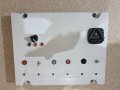
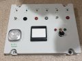
I have uploaded a pic of the front and underside of the front to my post, the only thing I have yet to mount to the lid will be a 2 gang single light switch that you would have at home for example.
Would any of you kind folks please draw me the best way to wire this thing up from the battery pack (just overdraw the screen with red for positive and black for negative)
To be honest im crap at reading schmeatics
I realise I will need a resister for each led, of which I would like to solder to a wire first and then solder the wire to the led leg
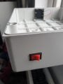
PS: I would also like to install a master on/off/kill switch on the base for whenever my son falls asleep when using to preserve the batteries
Reading top left to right the requested led colours are the following
I just had a look at a data sheet so hook the red switched wire to the rotary switch both pins marked 2, and also to pin 4.
The lamp will then wire from 1 to lamp nearest, 3 to next lamp and the other 1 to the last lamp.
The other side of the lamps will go to the common black wire.
I do not know what the lamps are. Are they LEDs and if so, do they have internal resistors of not?
Do you have any info on those 3 lamps?
The center lamp (pins 4 and 3) will be on until switched off and that switch bank in a normally closed one. At least, I think that is what will be.
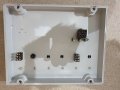
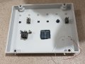
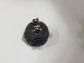
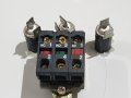
What’s that big thing in the upper right of the back picture? And what are the three things just below it? Oh, I can see from the front pic that you have more LEDs and the big thing is your rotary switch. That’s odd, because the back contacts don’t look like a rotary switch.
The LEDs aren’t clear enough in the picture to tell which leg is shorter. This is critical. It would be nice if you have mounted the LEDs so that the short leg is on the same side. Can you rotate them so this is how their mounted?
Given your answers, I can mark the picture up as I did to your original sketch. That sketch isn’t a schematic, but a point to point diagram as you asked. What about it wasn’t clear? Your answer will help me mark up the picture...
Also, if you could mark up the photo with where you’ll mount the battery pack and master switch, that will help, too. You can then take another picture of your marks.
Now for all of you lovely smart folks to show me how to wire this bad boy!!!
I have attached all the pics I hope will be enough info for your diagrams in point to point drawings,
***PLEASE NOTE I DO NOT HAVE ENOUGH COMMON SENSE TO KNOW HOW TO WIRE MULTIPLE CABLES OFF ONE CABLE***
All LEDs are standard 5mm and all + connections are to the left, the battery pack is a standard 4 way AA pack
I would prefer to solder requested resistors to a cable first and then to the led probes if at all possible
I.e Red cable to the + connection and White to the - connections
If possible can you folks also show me how to wire the traffic light lamps connected to the rotary switch, they appear to have 1 long short and 1 short leg.
Also, if you could please be so kind as to let me know the size of resistor I require for each LED, I realise that the colour of each LED requires a different resistor.
On top of this, can you please also show me via point to point diagram when pins on each switch connects to red or white wires
(or whatever colour of cables you suggest)
The push on - push off led light on the left hand bottom corner of the lid was orginally powered by 3 x 1.5v AAA batterys, however as you can see I have done away with those, and soldered some longer leads to the + and - connections on the pcb, I note that the existing pcb from that light has a tiny wee resistor (i'm guessing to reduce the voltage for the led?)
Guys, once again many thanks for all of your fantastic and informative help, I really am truly sorry for so many questions and my stupidy to date.
I do not know how to wire in series or paralell hence, the need for point to point and coloured cable drawings.
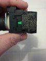
In relation to the 3 traffic lights for the rotary switch, I honestly do not know if they are lamps or leds?
I had a look at the writing on the side of them and they dont mention part numbers or anything like that, they just state the make of them
I honestly hope that all of the above wording and attached pics are enough for you smart folks to figure out and again I am very sorry for any silly statements on my part.
I just want to get this finished for my young son, all that is stopping me now is the actual wiring of said project
Here is a diagram.
As I do not know what your "Traffic Lights" are, that part is a bit of a guess.
In one of your other posts, the rotary switch had 3 banks all green. That would be better as I think the red bank will have the lamp on until it is operated. So if you can change the switch for the other one, that may be an idea.
Run one black wire around all the LEDS and just scrape a bit of insulation off at each point you need a connection if you do not want to join wires.
If you move the battery pack to the side near the switch, then the red wire from the battery will reach the switch.
All the resistors can be the same, and 470ohm will work. Lower it if you need more brightness. The calculated resistors mentioned for 20mA will be the minimum value you should go to. There is no reason to run the LEDs at 20mA. A lot less current will be ok, as long as they are bright enough. Try some resistors and see. Just do not go too low a value that will over stress the LEDs.
 Facebook
 Google
 GitHub
 Linkedin


")