Audio Amplifier

MrSalts

Joined Apr 2, 2020
2,767
Did you notice that it is drawn positive-at-the-top, unlike most Germanium circuits which are drawn the other way round?
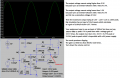
Yes, the redrawn version on Wikimedia claims it is from the Lin patent but there seem to be some minor differences. But yes, it is interesting that the schematic in the patent (drawing attributed to his attorney) uses positive on top format.

It would be interesting if an attorney's drawing set the standard.
 
Last edited:

MrAl

Joined Jun 17, 2014
13,703
Hi, I simulated it on Proteus and unfortunately those transistors are not available on the library. I tried using different ones but I don't know how to pick and use the right one for the circuit. We are just tasked to simulate the circuit and observe the waveforms. It's actually an experiment. I appreciate your comment.
Hello again,

Well if you cant find a model that is already in the library then you can create a model yourself by looking up the specs for the transistor and going from there.

Since the base emitters are always forward biased and the collector base of the transistors never (or should never) go into saturation, to get an approximate model you can find a regular transistor in the library that has specs that match the required transistor approximately, then place a 0.2 volt voltage source in series with each emitter. That will approximate the behavior so you can at least get some idea what will happen with that circuit.
For the PNP the 0.2v voltage source goes in series with the emitter such that the positive (+) terminal of the source connects directly to the emitter, and for the NPN the 0.2v source goes in series with the emitter such that the minus (=) terminal of the source connects directly to the emitter.
One of the things about a germanium over a silicon transistor is that the germanium turns on with less voltage so the extra voltage source helps this happen with a transistor with higher nominal base emitter forward voltage.

The main difference between the regular silicon transistor and the germanium is the nominal forward voltage of the base emitter and the saturation voltage. The extra series voltage source mimics the lower voltage of the germanium as long as in the design the base emitter is always forward biased. If the output does not saturate then there should not be a problem with the saturation voltage specs.
There are other differences such as speed but for audio frequencies it probably wont matter too much so at least you can get some idea what is going on. The gain will be lower too so you may have to adjust the beta of each transistor to some lower value.
 
Last edited:

Audioguru again

Joined Oct 21, 2019
6,826
I have been designing and making audio amplifiers for 56 years but never with old germanium transistors. Why did your teacher find such an old circuit for your studies?
I changed the bootstrapping on my silicon transistors version of the circuit you posted so that the speaker has no DC in it.
 

Attachments

Thread Starter

Rallyrral

Joined Apr 4, 2022
14
Hello again,

Well if you cant find a model that is already in the library then you can create a model yourself by looking up the specs for the transistor and going from there.

Since the base emitters are always forward biased and the collector base of the transistors never (or should never) go into saturation, to get an approximate model you can find a regular transistor in the library that has specs that match the required transistor approximately, then place a 0.2 volt voltage source in series with each emitter. That will approximate the behavior so you can at least get some idea what will happen with that circuit.
For the PNP the 0.2v voltage source goes in series with the emitter such that the positive (+) terminal of the source connects directly to the emitter, and for the NPN the 0.2v source goes in series with the emitter such that the minus (=) terminal of the source connects directly to the emitter.
One of the things about a germanium over a silicon transistor is that the germanium turns on with less voltage so the extra voltage source helps this happen with a transistor with higher nominal base emitter forward voltage.

The main difference between the regular silicon transistor and the germanium is the nominal forward voltage of the base emitter and the saturation voltage. The extra series voltage source mimics the lower voltage of the germanium as long as in the design the base emitter is always forward biased. If the output does not saturate then there should not be a problem with the saturation voltage specs.
There are other differences such as speed but for audio frequencies it probably wont matter too much so at least you can get some idea what is going on. The gain will be lower too so you may have to adjust the beta of each transistor to some lower value.
That's very helpful MrAi. I should probably study more about transistors. I only have the basic knowledge of it and not much on its application. Right now, it's quite difficult to study through online because of covid-19 ristrictions. This experiment was supposed to be done in actual but we can't.
 

Thread Starter

Rallyrral

Joined Apr 4, 2022
14
I have been designing and making audio amplifiers for 56 years but never with old germanium transistors. Why did your teacher find such an old circuit for your studies?
I changed the bootstrapping on my silicon transistors version of the circuit you posted so that the speaker has no DC in it.
Wow, that's pretty long. The circuit might have taken from an old textbook that's why. The experiment was supposed to be done in actual but we can't. We are in online class. I tried simulating your first modification and it worked. Unfortunately not when injected with 100mV, 1K Hz input. There is some kind of clipping, I think. We were actually given a procedure.
 

Attachments

Audioguru again

Joined Oct 21, 2019
6,826
I tried simulating your first modification and it worked. Unfortunately not when injected with 100mV, 1K Hz input. There is some kind of clipping, I think.
Of course you had clipping, the input signal level was too high and needed the volume control to be turned down.
Here is my original silicon transistors version with more notes added:
 

Attachments

MrAl

Joined Jun 17, 2014
13,703
That's very helpful MrAi. I should probably study more about transistors. I only have the basic knowledge of it and not much on its application. Right now, it's quite difficult to study through online because of covid-19 ristrictions. This experiment was supposed to be done in actual but we can't.
Hi,

Oh sorry to hear that. Yes covid has messed up many things for many people so we have to learn to adopt to the restrictions and cautions.
I read they are lifting the requirement for face masks on airplanes now in the US. Not sure if that when through yet though, but even if it didnt at laest someone is thinking about all this.

I understand about the transistor model problem it's not that easy to create a model i guess, but if that's a problem then just try connecting the small voltage sources (0.2 volts) in series with the emitters of regular silicon transistors as suggested in my last post. That should get you going.
The main thing that changes is the bias voltage level, so it's not too big of a deal.
If you need help finding the silicon transistors you could use for this im sure someone here can help you.

Good luck with your studies.
 

MrAl

Joined Jun 17, 2014
13,703
I have been designing and making audio amplifiers for 56 years but never with old germanium transistors. Why did your teacher find such an old circuit for your studies?
I changed the bootstrapping on my silicon transistors version of the circuit you posted so that the speaker has no DC in it.
Hey there AG,

Ha ha, so along with the LM358 and similar you also dont like germanium transistors. Ok no problem.

I will say though that some years ago when white LEDs were first becoming available, myself and a couple others turned to germanium transistors to make an LED flashlight boost circuit to drive the LED from one or two AA cells. Back then many flashlight users wanted to get every bit of energy form their batteries before they had to throw them away, but also wanted to get the start up voltage as low as possible. The lower forward voltage of the base emitter of the germanium transistor makes it possible to get the circuit to start up with very low voltage. It worked out ok in the long run.
Today i have several small LED lights that have a problem starting with lower voltage. What this means is that when you turn the flashlight off you cant turn it back on, even though it could still run for an hour more. It's a real pain sometimes. I had to go to a 3xAA flashlight for some things because i could not stand that startup problem anymore and it is hard to add a circuit to a small manufactured light.

As i always like to say, each part has it's own niche application, some have a wider application range of course but others may fit the bill in certain applications.

It may be of interest to mention that germanium transistors were being considered for use in hybrid germanium/silicon combination transistor. The idea was to get the high speed of the silicon while getting the lower voltage benefit from the germanium and thus get higher efficiency.

There is an interesting article at spectrum-ieee-org that talks about these ideas. The article starts out with:
"Germanium Takes Transistors Where Silicon Cant".
It's a somewhat recent article too not from the 1960's. I'd say sometime after 2015.
 
Top