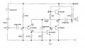
Can you explain your design that uses an 18 ohm resistor to bias the 1.2v between the bases of Q3 and Q4? To get to 1.2v, you'd need 666mA of current. You are limiting current of your 6-volt supply with a 330 ohm resistor so you can't get to the 666mA. Your without proper bias, crossover distortion will be huge.
your 330 ohm resistor to bias your output transistors is connected through your speaker to put a constant dc bias on the speaker (typically a bad idea).
I could continue but I don't want to type more but you have problems with your input stage and mid-stage as well.
There is only about 8mA in the 330 ohms resistor (8mA x 330= 2.64V) which bootstraps the signal driving the base of the NPN output transistor higher than the supply voltage. Low power amplifiers 55 years ago were built like that.
I agree that there will be a lot of crossover distortion.
Have you used LT Spice simulator? You can create a schematic there and pass it to here.
A lot of people have this installed already so they can take a better look at your circuit problem.
It does look like an unusual design though. Were their any specific goals or specs that were to be met with this design?
The top of R5 would normally be driven from a bootstrap circuit from the output, this is just a cheap way of avoiding the bootstrap capacitor in the days whey they might have been expensive by using the speaker coupling capacitor as the bootstrap capacitor.
It would work with silicon transistors if you replace the 18Ω resistor with two 1N4148 diodes in series. It does have feedback, so, although there will be some crossover distortion, it will be somewhat reduced by the feedback.
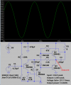
I used modern silicon transistors and changed a few resistor values to match them. I increased capacitor values so that it can play low frequencies. I used two diodes instead of the 18 ohms resistor and the resulting small amount of crossover distortion can be eliminated with a resistor in series with the diodes. Now it can wake the dead with its massive 1/4W output.
Can you explain your design that uses an 18 ohm resistor to bias the 1.2v between the bases of Q3 and Q4? To get to 1.2v, you'd need 666mA of current. You are limiting current of your 6-volt supply with a 330 ohm resistor so you can't get to the 666mA. Your without proper bias, crossover distortion will be huge.
your 330 ohm resistor to bias your output transistors is connected through your speaker to put a constant dc bias on the speaker (typically a bad idea).
I could continue but I don't want to type more but you have problems with your input stage and mid-stage as well.
Thank you so much MrSalts for your comment. I really appreciate your help. There's maybe wrong with the circuit. I still have a very little understanding about it. It's very nice to be here.
Have you used LT Spice simulator? You can create a schematic there and pass it to here.
A lot of people have this installed already so they can take a better look at your circuit problem.
It does look like an unusual design though. Were their any specific goals or specs that were to be met with this design?
Hi, I simulated it on Proteus and unfortunately those transistors are not available on the library. I tried using different ones but I don't know how to pick and use the right one for the circuit. We are just tasked to simulate the circuit and observe the waveforms. It's actually an experiment. I appreciate your comment.
The top of R5 would normally be driven from a bootstrap circuit from the output, this is just a cheap way of avoiding the bootstrap capacitor in the days whey they might have been expensive by using the speaker coupling capacitor as the bootstrap capacitor.
It would work with silicon transistors if you replace the 18Ω resistor with two 1N4148 diodes in series. It does have feedback, so, although there will be some crossover distortion, it will be somewhat reduced by the feedback.
I used modern silicon transistors and changed a few resistor values to match them. I increased capacitor values so that it can play low frequencies. I used two diodes instead of the 18 ohms resistor and the resulting small amount of crossover distortion can be eliminated with a resistor in series with the diodes. Now it can wake the dead with its massive 1/4W output.
Hi, Sir.
This is very helpful. You really simulated it for the sake of helping me. That is very kind of you. I will try to simulate your modified circuit on Proteus. Thank you!
I think it's in Linsley-Hood's books, because he covers quite a bit of history.
Did you notice that it is drawn positive-at-the-top, unlike most Germanium circuits which are drawn the other way round?
Lin uses a separate bootstrap from the output coupling capacitor. Using the coupling cap as the bootstrap may be a short-cut, or it may be an attempt to circumvent the patent.
 Facebook
 Google
 GitHub
 Linkedin
 180.7 KB Views: 71