Attenuation of a signal using a hex inverter ..#2

MrChips

Joined Oct 2, 2009
35,022
Ch 2 works. I think I did everything else. Putting source to LINE allows the trigger controls to work better.
Now it’s scrolling to the right when I pluck a string, it wasn’t going that before. this is just 3 stages in series.
No. You do not normally set the source trigger to LINE. It should be set to INT.

You said that you do not know what most of the controls of the oscilloscope do. That is a sad mistake. You should/must become confident in using your oscilloscope by learning the function of each and every control.

Acquiring a new and modern digital oscilloscope is not going to make this situation any better.
 

Thread Starter

rpschultz

Joined Nov 23, 2022
851
I appreciate all the help. Unfortunately it's getting worse, I can't get it to display anything near what I did yesterday in posts 44, 50, etc. It's getting fuzzier and won't stop scrolling. Ch2 is a little better than Ch1, not good though. I've tried all the suggestions from @sarahMCML, @MrChips, @Ian0, etc. I'll have to get it fixed or find another scope.
 

MrChips

Joined Oct 2, 2009
35,022
The problem is not with the oscilloscope. The problem is with the user.

There are three fundamental sections in the oscilloscope:
1) Vertical amplifiers
2) Horizontal sweep
3) Trigger

Of the those three, the trigger section is the most important one. Take the time to master all the controls and settings of the trigger section.

The problem does not go away with a new scope.
 

Thread Starter

rpschultz

Joined Nov 23, 2022
851
OK I was able to get it to work decently.
  • There is a narrow band of Trigger LEVEL and VAR HOLDOFF that gave a decent image.
  • Each note/frequency had different trigger levels.
  • Decent image doesn't last long, as the note decays it gets jittery again.
  • Sometimes Auto mode works better than Norm, but usually manual trigger levels work best.
  • I also think I'm picking up some interference, moving my test leads around sometimes makes it better/worse.

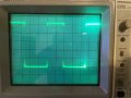
Here's a good image. Vertically this is 1V/division. @sarahMCML circuit in post #30 (without voltage divider) is powered at 5v.
Horizontally: 2ms/division. 4.5 div is 9ms, or 111 Hz. It was an open A tuned to 110 Hz, so that makes sense. Curious why the waveform isn't symmetric.
IMG_5827.jpg
 

Ian0

Joined Aug 7, 2020
13,228
OK I was able to get it to work decently.
  • There is a narrow band of Trigger LEVEL and VAR HOLDOFF that gave a decent image.
  • Each note/frequency had different trigger levels.
  • Decent image doesn't last long, as the note decays it gets jittery again.
  • Sometimes Auto mode works better than Norm, but usually manual trigger levels work best.
  • I also think I'm picking up some interference, moving my test leads around sometimes makes it better/worse.

Here's a good image. Vertically this is 1V/division. @sarahMCML circuit in post #30 (without voltage divider) is powered at 5v.
Horizontally: 2ms/division. 4.5 div is 9ms, or 111 Hz. It was an open A tuned to 110 Hz, so that makes sense. Curious why the waveform isn't symmetric.
View attachment 330728
It's not symmetric because the threshold of the inverter can be anywhere between 30% and 70% of supply voltage.
If you want it symmetric, the best you will get is to use a CMOS-555 or a comparator connected as a Schmitt trigger.
 

sarahMCML

Joined May 11, 2019
703
OK I was able to get it to work decently.
  • There is a narrow band of Trigger LEVEL and VAR HOLDOFF that gave a decent image.
  • Each note/frequency had different trigger levels.
  • Decent image doesn't last long, as the note decays it gets jittery again.
  • Sometimes Auto mode works better than Norm, but usually manual trigger levels work best.
  • I also think I'm picking up some interference, moving my test leads around sometimes makes it better/worse.

Here's a good image. Vertically this is 1V/division. @sarahMCML circuit in post #30 (without voltage divider) is powered at 5v.
Horizontally: 2ms/division. 4.5 div is 9ms, or 111 Hz. It was an open A tuned to 110 Hz, so that makes sense. Curious why the waveform isn't symmetric.
View attachment 330728
With plucked guitar notes the different amplitudes will need varying trigger level settings to give a stable display, and as the note fades away the scope will lose lock. This is the advantage of a digital scope, you can set it for single shot and it will store the triggered sweep.
Setting trig levels takes a bit of getting used to, but it's worth just putting a signal or pulse generator on one channel and playing around until you get more confident on how all the variables interact with each other.
 

atferrari

Joined Jan 6, 2004
5,020
Wondering what could be the advantage of implement this with a logic IC when an opamp would fit easily.

The first it comes to mind is an amplifier that can vary gain and even phase of the output with a simple pot (or preset). Implemented one myself a decade ago in a signal generator.

If you, the OP, say I want to do it just because, I have nothing to add.
 

Ian0

Joined Aug 7, 2020
13,228
Wondering what could be the advantage of implement this with a logic IC when an opamp would fit easily.

The first it comes to mind is an amplifier that can vary gain and even phase of the output with a simple pot (or preset). Implemented one myself a decade ago in a signal generator.

If you, the OP, say I want to do it just because, I have nothing to add.
It was my suggestion, on a different thread, and the reasoning behind it is rather lost in the mists of time. The application is for frequency measurement. The 74HCU as a linear amplifier tends to run out of gain as the output approaches the supply rails, rather than clip, but it remains monotonic, although not very linear. Therefore it acts a compressor, reducing the dynamic range of the signal, which should make it easier to determine the frequency, as the zero crossing detector doesn’t have to cope with such a large signal range.
 

Thread Starter

rpschultz

Joined Nov 23, 2022
851

Thread Starter

rpschultz

Joined Nov 23, 2022
851
It was my suggestion, on a different thread, and the reasoning behind it is rather lost in the mists of time. The application is for frequency measurement. The 74HCU as a linear amplifier tends to run out of gain as the output approaches the supply rails, rather than clip, but it remains monotonic, although not very linear. Therefore it acts a compressor, reducing the dynamic range of the signal, which should make it easier to determine the frequency, as the zero crossing detector doesn’t have to cope with such a large signal range.
The reason is because of the poor quality ADC's in cheap microcontrollers (arduino, ESP32, etc). Originally I was using an LM358, allowing it to clip the signal naturally to account for a large range of gain from various guitar pickups. Then @Jerry-Hat-Trick suggested using digitalRead, saying it would be way faster than analogRead - and using a hex converter can convert the signal to HIGH, LOW for the digitalRead. So I then accidentally hijacked a similar thread and an admin moved it to this standalone thread. So a week later, I finally figured out how to get a nice square wave and view it on a CRO - thanks to a lot of help from the good people here.
 

sparky 1

Joined Nov 3, 2018
1,218
A UO4 inverter having gain G<1 is an attenuator. G = –RF/RG
With guitar the 2N5457 and other JFETs have been popular in pedals.
It starts with measuring the pinch off voltage, I think mixing 2 waves, for example a sine wave and a square wave
the result is a construction of a wave can have varying amounts of square edges.
It is easy to buy a pedal pcb that does that or modify it. Working the inverting gain could come from that.
The numbers tell you something about the structure of attenuation with U04.

search for a circuit using 2N5457 for guitar. This instruction leads to "wiggle voltage" talking about microphone audio.
making a circuit that is getting ready for awesome guitar effects is same. Overall profesional musicians pay for specific skill set.
Video on pinch off voltage and gain less than 1,,, selecting the right resistors is for you to discover.
Resistor values is what makes this circuit ideal for guitar. As a platform to get started making very nice guitar affects.
 
Last edited:

Thread Starter

rpschultz

Joined Nov 23, 2022
851
search for a circuit using 2N5457 for guitar. This instruction leads to "wiggle voltage" talking about microphone audio.
making a circuit that is getting ready for awesome guitar effects is same. Overall profesional musicians pay for specific skill set.
Video on pinch off voltage and gain less than 1,,, selecting the right resistors is for you to discover.
Resistor values is what makes this circuit ideal for guitar. As a platform to get started making very nice guitar affects.
Thanks for the replay. I've used a 2N5457 in a couple pedals, most often instead of an opamp, like in the the Catalinbread CB30 (Brain May). Great video, I'll have to study that.
 

Thread Starter

rpschultz

Joined Nov 23, 2022
851
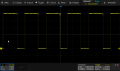
Here's something similar to post 66 on my new SDS804. A lot of trigger options and settings to learn.

Roughly 9 division at 5ms/div is 45 ms or 111 Hz. That's an open A at 110 Hz. Cool. The math checks out. Oh, I just realized it did the math for me and somehow knows the frequency is 109.9 Hz.
SDS804X_HD_PNG_6.png
 

Thread Starter

rpschultz

Joined Nov 23, 2022
851
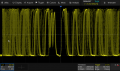
I have tried to measure the noise in this system, when no signal is coming in. But any noise going through the 74HCU04 is amplified to either GND or 3v3. Just looks like a big block. But if I zoom in, I can find a "noise" frequency. The rough period is similar to the 200 ns division, which is 5 Mhz.
Does this mean anything?

SDS804X_HD_PNG_16.png

I removed the 10M resistor to see what the noise level is without it, I'm not sure if this is the actual noise level. Roughly 25-30 mV.SDS804X_HD_PNG_7.png

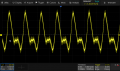
here is a D string on one of my guitars. no amplification, no hex inverter, straight out of the jack. Same scale. About 60-70 mV total. This is on the low side of pickups that I have measured.SDS804X_HD_PNG_13.png
 

Ian0

Joined Aug 7, 2020
13,228
Are you still working on a breadboard? In which case it is probably caused by lack of decoupling. Multiple stages in a HCU04 can couple back through the supply pins and make a high-frequency oscillator if you are not careful.
It would work best if you amplify it with the HCU04 until the output reaches full supply voltage, but is still a bit rounded at the corners, then add a HC14 Schmitt trigger.
You need to check what happens with a real guitar signal which is full of harmonics, just to make sure when you have finished processing it the squarewave is at the fundamental frequency, and doesn't have any transitions caused by the harmonics.
 

Thread Starter

rpschultz

Joined Nov 23, 2022
851
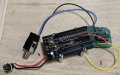
Here's my current setup (not a breadboard). I had a few prototype PCB's printed using a previous LM358 design. I used part of that circuit (PS filtering and power regulation) and then added 74HCU04 chip as a side perfboard, using a 3v3 regulator for power. This picture is missing the 10Meg resistor that I added later, but it has HPF/LPF on the input before the 74HCU. The yellow wire is the output of the 74HCU and was eventually soldered to the PCB taking the signal into the MCU.

The picture in post 75 is an actual guitar signal through this setup. I calculated the frequency as 111 Hz, then realized that my scope did it for me (109.9 Hz). Open A ideally is 110.0 Hz.

IMG_5861.jpg
 

Thread Starter

rpschultz

Joined Nov 23, 2022
851
Multiple stages in a HCU04 can couple back through the supply pins and make a high-frequency oscillator if you are not careful.
It would work best if you amplify it with the HCU04 until the output reaches full supply voltage, but is still a bit rounded at the corners, then add a HC14 Schmitt trigger.
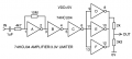
I've wondered about this. @sarahMCML suggested the below configuration, and so that is what I'm using (without voltage divider at the end since Vdd=3v3). The parallel stages at the end are for increasing the current output, up to 5 mA/stage. But you're suggesting that if this isn't necessary, it could be bad. I'll have to do some more testing...
1726157310802.png

The next thing you mention is a HC14 Schmitt trigger, which seems similar to the 74HCU04. What would be the advantage of using them both?
 
Top