Facebook
 Google
 GitHub
 Linkedin
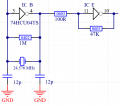
I'm trying to simulate the 74HCU04 in Spice. I have the model file. What type of component is used? When I pull an INVERTER, it doesn't look like the one in post #1.
Mod:link to old thread
https://forum.allaboutcircuits.com/...gnal-using-a-hex-inverter.195599/post-1846338
Mod:link to old thread
https://forum.allaboutcircuits.com/...gnal-using-a-hex-inverter.195599/post-1846338
Last edited by a moderator: