Attenuation of a signal using a hex inverter ..#2

Thread Starter

rpschultz

Joined Nov 23, 2022
851
Currently:
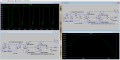
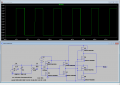
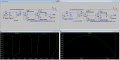
There's this blip on the bottom of the squarewave output of the CMOS. If I increase the sine amplitude, it tends to go away. The top is nice and square from the zener. Any ideas on how to fix the bottom?
The right plots show the band pass at values that work well.
1724954241664.png
 

Attachments

Thread Starter

rpschultz

Joined Nov 23, 2022
851
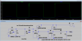
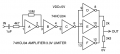
Well, increasing the gain of the CMOS works. Using 10Meg instead of 1Meg. Though the application note says you can simply apply 1 resistor across multiple stages, that doesn't work. Each stage needs it's own resistor.
1724959525487.png
 

sarahMCML

Joined May 11, 2019
703
Your circuit in post #9 works perfectly if you use two straight inverter stages after the first with the 10M feedback resistor. I then fed the output from the third stage into the paralleled combination of the last three gates to use them as a booster stage. From there to a 2k in series with a 3k3 to ground, the midpoint gives you a limited 3.3V max into your micro!
 

Ian0

Joined Aug 7, 2020
13,230
I would have used a 3V or 3.3V supply for the 74HCU04. They tend to run a bit warm in linear mode on 5V, especially with two inverters in linear mode.
It works nicely with a sinewave, but what happens when you feed it with a guitar signal rich in harmonics?
 

Thread Starter

rpschultz

Joined Nov 23, 2022
851
Your circuit in post #9 works perfectly if you use two straight inverter stages after the first with the 10M feedback resistor. I then fed the output from the third stage into the paralleled combination of the last three gates to use them as a booster stage. From there to a 2k in series with a 3k3 to ground, the midpoint gives you a limited 3.3V max into your micro!
I would like to study this, but can't follow. Can you post a schematic picture?
 

Thread Starter

rpschultz

Joined Nov 23, 2022
851
I would have used a 3V or 3.3V supply for the 74HCU04. They tend to run a bit warm in linear mode on 5V, especially with two inverters in linear mode.
So 3.3v regulator. Sparkfun carries the LD1117V33. Or Amazon has them cheaper. I don't know much about regulators. The TO220 package has an output of 800 mA which should be plenty.
 

Ian0

Joined Aug 7, 2020
13,230
So 3.3v regulator. Sparkfun carries the LD1117V33. Or Amazon has them cheaper. I don't know much about regulators. The TO220 package has an output of 800 mA which should be plenty.
Two main things to note about regulators:
1. put a capacitor on the output. The datasheet will tell you what size, but 10uF aluminium electrolytic is usually correct.
2. Makes sure that (Input Voltage– Output Voltage > dropout voltage.
LD1117 is a good one.
 

Thread Starter

rpschultz

Joined Nov 23, 2022
851
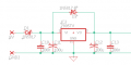
Here's the PS section of the circuit that I've been using with the 7805.
Dropout voltage on the LD1117 is 1V. So 9v-3v3 is 5.7v. So that's bigger than the 1v dropout. Thanks. I learned something today!
1725023202591.png
 

sarahMCML

Joined May 11, 2019
703
Huh. Here is 2 in series into 2 in parallel - without the voltage divider. The application notes suggest parallel stages for higher current loads, not sure if I need that or not. But interesting you only put the 10Meg on the first stage. I'll have to play around with this.

Thanks for the help!

View attachment 330506
I tried it with another 10M resistor on the second stage and it made no difference to the output, so I removed it. I used all three gates in parallel on the output for the very reason the app notes stated: more current to drive the two resistor divider.
It's extremely sensitive, I still get perfectly square switching with a 10mV p-p 1KHz sine wave input, although the mark/space ratio is off, being about 66% high, 33% low. It needs 100mV p-p to get back to 50/50 mark/space.
 

Thread Starter

rpschultz

Joined Nov 23, 2022
851
I tried it with another 10M resistor on the second stage and it made no difference to the output, so I removed it. I used all three gates in parallel on the output for the very reason the app notes stated: more current to drive the two resistor divider.
It's extremely sensitive, I still get perfectly square switching with a 10mV p-p 1KHz sine wave input, although the mark/space ratio is off, being about 66% high, 33% low. It needs 100mV p-p to get back to 50/50 mark/space.
Yes I noticed sensitivity at lower than 100mvPP signals too. I'll play with some smaller signals using your design.,
I'm likely going to switch to a 3v3 voltage regulator so I won't need the voltage divider at the end.
 

MrAl

Joined Jun 17, 2014
13,775
Well, increasing the gain of the CMOS works. Using 10Meg instead of 1Meg. Though the application note says you can simply apply 1 resistor across multiple stages, that doesn't work. Each stage needs it's own resistor.
View attachment 330456
The higher gain allows for more amplification, but the tradeoff is bandwidth vs amplification.

I would think a single resistor would work if the DC offsets where matched, which could be impossible to get right in the real world. You could try, but the results may change with temperature. You could also try capacitively coupling the two stages that reduces any problems with DC input offsets. That's if you need that of course.
 

MrAl

Joined Jun 17, 2014
13,775
Kind of.
I’ve tried:
3 in series
2 series + 2 parallel.
Both give me garbage.

only 2 in series alone works.
Maybe check for some DC offset. If the gain is too high it could cause problems, and 3 in series would have exceptionally high gain.
 

sarahMCML

Joined May 11, 2019
703
Did you use exactly my circuit, or with any modifications?
I used an old Motorola MC74HCU04, the only one I have. I only got the oscillation that you see when I tried a version without the 4k7 resistor in series with the input capacitor! Otherwise there was no sign of spurious oscillations.
 

Thread Starter

rpschultz

Joined Nov 23, 2022
851
Did you use exactly my circuit, or with any modifications?
I used an old Motorola MC74HCU04, the only one I have. I only got the oscillation that you see when I tried a version without the 4k7 resistor in series with the input capacitor! Otherwise there was no sign of spurious oscillations.
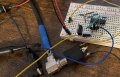
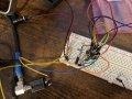
ok I just tried the whole thing, all 6 stages, except the voltage divider at the end. Same thing. I can’t do more than 2 stages in series without it looking like post 35.

IMG_5809.jpeg
 
Top