Attenuation of a signal using a hex inverter ..#2

joeyd999

Joined Jun 6, 2011
6,443
Did you use exactly my circuit, or with any modifications?
I used an old Motorola MC74HCU04, the only one I have. I only got the oscillation that you see when I tried a version without the 4k7 resistor in series with the input capacitor! Otherwise there was no sign of spurious oscillations.
Hi-speed CMOS will not work as a linear amp. IIRC, it only worked well with CD4000 (unbuffered) series logic (which is equivalent to the single stage inverters that you have simulated in the thread above).

Edit: the 74HCU may work.

 

sarahMCML

Joined May 11, 2019
703
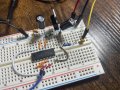
Looking at your layout, a number of things stand out.
1) No decoupling capacitors across the pins of the 7805 regulator, which may well be oscillating or allowing the '04 to do so.
2) The interconnecting wires being long loops could also be giving problems. I linked mine with small resistor pin offcuts to minimise path length.
3) Is that really a 10Meg resistor across the first gate? I can see that the series resistor is 5k1.
 

Thread Starter

rpschultz

Joined Nov 23, 2022
851
Ok I cleaned up my breadboard. Yes that is a 10Meg (I measured). 100u and 100n on both input and output.
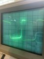
IMG_5810.jpeg

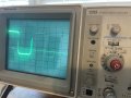
this is 3 in series. Low E, 82.4 hz.
IMG_5813.jpeg

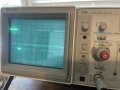
This is 3series+3parallel. I think it’s my scope. The wave is so square that it can’t display the vertical parts? But the filtering probably helped.
IMG_5811.jpeg
 

sarahMCML

Joined May 11, 2019
703
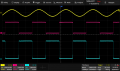
Just for interest, here's the output of mine.
The yellow trace is 200mV P-P at ~86Hz, the purple is the 3.3V output from the three paralleled buffers, and the cyan is the 5V output from the third inverter before the buffers.

SDS2504X Plus_PNG_8.png
 

Thread Starter

rpschultz

Joined Nov 23, 2022
851
Wow, I need a digital scope. Hopefully I can pull the trigger on one soon.

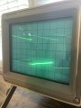
This is how I have it setup, I don’t understand some of the knobs. Ch2 doesn’t work.
IMG_5816.jpeg
 

MrChips

Joined Oct 2, 2009
35,031
You still have CH1 input set to AC.
Set it to DC.

You have VERTICAL MODE set to CH1, ADD.
Set it to BOTH, ALT or CHOP.
 

sarahMCML

Joined May 11, 2019
703
As MrChips suggests, but also, go to the Trigger area on the far right, turn Variable Hold Off fully Anti-Clockwise, the Mode switch to Norm (the display will probably disappear!), and then adjust the Trig Level control to get a nice, stable display back.
 

MrChips

Joined Oct 2, 2009
35,031
The second line is for CH2.
Now connect a probe to CH2 and connect both probes to the same source.

(I am simply checking to see if CH2 actually works.)
Set CH2 the same as CH1.
All the red knobs should be turned fully clockwise until they "click".
 

Thread Starter

rpschultz

Joined Nov 23, 2022
851
As MrChips suggests, but also, go to the Trigger area on the far right, turn Variable Hold Off fully Anti-Clockwise, the Mode switch to Norm (the display will probably disappear!), and then adjust the Trig Level control to get a nice, stable display back.
Ok. Norm. It’s flaky. Adjusting the VAR and LEVEL is hit or miss on the trigger. Either way it does t seem to help.
 

Thread Starter

rpschultz

Joined Nov 23, 2022
851
Just for interest, here's the output of mine.
The yellow trace is 200mV P-P at ~86Hz, the purple is the 3.3V output from the three paralleled buffers, and the cyan is the 5V output from the third inverter before the buffers.

View attachment 330609
what scope is this? 2 ch? Or 4?
I’m getting real close to buying a Siglent SDS802x HD. But I could only display 2 of those 3 traces, right?
 

sarahMCML

Joined May 11, 2019
703
As a test, can you connect to your sine input, adjust for a decent sized display, then try to use Trig Level variable pot. You should see the front edge of the sine wave moving up and down as you adjust the level.
My scope is a Siglent SDS2104X Plus, 4 Channel, Upgraded.
 

MrChips

Joined Oct 2, 2009
35,031
So far, your oscilloscope trace looks normal.
The problem is with the camera used to take the photographs.
If the Horizontal SEC/DIV is set at 2ms, then the photos suggest that the camera shutter speed is about 10 ms or 1/100 s.
You need to use a camera that allows you to manually set the shutter speed and aperture.
 

Thread Starter

rpschultz

Joined Nov 23, 2022
851
So far, your oscilloscope trace looks normal.
The problem is with the camera used to take the photographs.
If the Horizontal SEC/DIV is set at 2ms, then the photos suggest that the camera shutter speed is about 10 ms or 1/100 s.
You need to use a camera that allows you to manually set the shutter speed and aperture.
I understand what you’re saying, but the photos look the same as they look to my eye
 

Thread Starter

rpschultz

Joined Nov 23, 2022
851
Ch 2 works. I think I did everything else. Putting source to LINE allows the trigger controls to work better.
Now it’s scrolling to the right when I pluck a string, it wasn’t going that before. this is just 3 stages in series.

Here’s a video
Video
 

sarahMCML

Joined May 11, 2019
703
Your Source lever switches on the lower right hand side should be set to Internal, and Vertical Mode there to "Ch1". Switch Channel 1 back to "Ch1" rather than "Both" in the left panel. I usually leave the "Add-Alt-Chop" switch in the "Chop" position for slow time base settings.
 
Top