Astable Ocsilator & 555 timer

Thread Starter

hawk7890

Joined Mar 21, 2011
9
Good day,

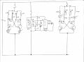
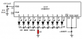
I have 2 simple circuits, one is an astable Oscilator with 2 transistors, and 2 variable resistors for the speed. On the same battery set (6x 1.5v) I have a chaser with a 4017 chip driven by a 555 timer.

The issue I have is when I increase the Oscilation speed, the 555 timer speed is also affected.

I tried with the NPN and the PNP versions of the oscilators.

Anyone have an idea why this is happening and how I can rectify it?
 

Audioguru again

Joined Oct 21, 2019
6,674
An ordinary LM555 or NE555 is very old and produces a 400mA supply current load each time the output switches. Your battery drops its voltage each time the 555 overloads it with the 400mA surge. Use a modern Cmos 555 instead (LMC555, TLC555 or ICM7555).
 

Attachments

Audioguru again

Joined Oct 21, 2019
6,674
I forgot to say that for my chasers, I use a Cmos Schmitt-trigger inverter as the oscillator to the 74HC4017 and a couple of the Cmos inverters to pulse the LEDs common so that the LEDs each blink for a short duration, reducing the average battery current.
The 74HC4017 is Cmos but with an output current high enough (20mA to 25mA) to brightly light the LEDs.
I Use a couple more of the Cmos inverters to allow a pause for 2 seconds after the chaser goes around 5 times to reduce the average battery current even more. Two (for red LEDs) alkaline AA cells or four (for bright green or blue LEDs) alkaline cells last for 3 months.
 

ElectricSpidey

Joined Dec 2, 2017
2,758
Seems odd because the frequency of a 555 is supposed to be independent of the supply voltage.

Do you have the proper de-coupling capacitor on the 555 power pins?
 

Thread Starter

hawk7890

Joined Mar 21, 2011
9
Thank you for your responses.
Unfortunately I only have NE555 timers on hand.
my 555 circuit is as follows:
pin5 -> .01uf ceramic cap -> gnd
vcc-> 10k res -> pin7-> 10kpot->pin 2,6 -> 10uf -> gnd
pin1 -> gnd, Pin 4,8 -> vcc
pin3 -> 14 of 4017

I will try the 2 caps idea. Do I just put them anywhere along the circuit? Can they be right at the power source?

My project is the following:
  • a 4017 driven by a 555 timer (I will research the schmitt trigger alternative)
  • 1 astable multivibrator using NPN transistors 47k resistor in series with 10K pots, 22uf caps and 470ohm resistor.
  • another astable multivibrator with same components but using a dual LED with common ground, it is between the Emitters and Ground. (I tried with a PNP astable multivibrator with the same result)
 

MrChips

Joined Oct 2, 2009
30,720
I will try the 2 caps idea. Do I just put them anywhere along the circuit? Can they be right at the power source?
The 0.1μF capacitors should go across the IC Vcc and GND pins of the IC that is causing the problem and the IC that is sensitive to the problem. Ideally, 0.1μF capacitors should be placed across Vcc (or VDD) and GND of every IC.

Put the 10μF capacitor across Vcc and GND of the NE555 timer IC.
 

Audioguru again

Joined Oct 21, 2019
6,674
The capacitors for the power supply batteries should be near the NE555 that is drawing very high current pulses.
Since you did not post a schematic then your transistors also might be drawing very high current pulses.

You should use a Cmos oscillator to drive the Cmos CD4017 IC. Here it is:
 

Attachments

crutschow

Joined Mar 14, 2008
34,285
A small resistor (e.g. 10 ohms) connected in series with the power before the power-to-ground decoupling capacitor at the 555 power pin may also help.
The idea is to isolate the power to the 555 as much as possible from any noise or spikes generated elsewhere.
 

MrChips

Joined Oct 2, 2009
30,720
Try and get LMC555 or TLC555 instead of NE555.
LM555 and NE555 are notorious for generating noise on the supply lines.

Anytime you have a circuit that is dependent on RC switching thresholds you can expect that the trigger will occur earlier than expected if there is a clock signal happening around the same time.

To elaborate, the voltage on the RC circuit is slowing rising or falling towards a threshold voltage. Any noise in the system will cause the RC circuit to trigger earlier than the designed time. This will result in inconsistent timing behavior.
 

dl324

Joined Mar 30, 2015
16,846
4017 driven by a 555 timer (I will research the schmitt trigger alternative)
The outputs of a bipolar 555 timer aren't guaranteed to be able to drive the inputs of CD4xxx logic. It will usually work, but good designs won't count on that.
1 astable multivibrator using NPN transistors 47k resistor in series with 10K pots, 22uf caps and 470ohm resistor.
If you're not going to post schematics, you shouldn't bother trying to discuss circuits. Most will have an idea of what you're talking about with this astable because we're familiar with the circuit, but it's better to be crystal clear and use schematics. Well drawn schematics are best.
 

Audioguru again

Joined Oct 21, 2019
6,674
I simulated a typical 2-transistors multivibrator circuit. The parts were so identical that both transistors turned on at the same time and did not oscillate. I increased the value 10% for one capacitor and the circuit oscillated every time.
 

Thread Starter

hawk7890

Joined Mar 21, 2011
9
Good day all.

Attached is my circuit. The NPN transistors are C1214. The multivibrator that affects the chaser is the one on the left. I have also tried the PNP version where the circuit would be identical to the one on the right with the only difference that the power is reversed. On the NPN I have also tried with the LEDs in series with the 470 resistor with the same issue.
 

Attachments

dl324

Joined Mar 30, 2015
16,846
Attached is my circuit.
I see nothing that would cause the behavior you describe. Decoupling capacitors have been suggested 3 times. Have you installed one?

The oscillator on the right will be problematic with a 9V power supply. The B-E junctions will breakdown at 5V of reverse bias and beta will be affected. The circuit on the left will be okay because you have two PN junctions in series and the total breakdown voltage will be higher than 9V.

I've found the circuit on the right to be problematic because the off LED can be on when it shouldn't.
 

Audioguru again

Joined Oct 21, 2019
6,674
Why do you use a diode in series with each LED on the CD4017?
Diodes are not needed since the 4017 produces only one output at any time.

But you might be over-heating the 4017more than its absolute max of 100mW with your 9V supply.
A red LED might have a forward voltage of 1.8V and the output of a 4017 might be 18mA. Then the 4017 heats with(9V - 1.8V) x 18mA= 130mW. Connect all LED cathodes together and use a single 68 ohms resistor from the cathodes to ground for red LEDs.
For 3.2V blue or white LEDs the heating of the 4017 will be only (9V - 3.2V)/15mA= 87mW then a resistor is not needed.
 

Attachments

Thread Starter

hawk7890

Joined Mar 21, 2011
9
I see nothing that would cause the behavior you describe. Decoupling capacitors have been suggested 3 times. Have you installed one?

The oscillator on the right will be problematic with a 9V power supply. The B-E junctions will breakdown at 5V of reverse bias and beta will be affected. The circuit on the left will be okay because you have two PN junctions in series and the total breakdown voltage will be higher than 9V.

I've found the circuit on the right to be problematic because the off LED can be on when it shouldn't.
Thanks Dennis,
I am not a pro when it comes to electronics, I have a basic understanding. Can you tell me where in my diagram to put the decoupling capacitors? For the circuit on the right, what would be the way to fix it? The reason the one on the left is different is because I am using a 2 color led with a common ground.
 

Thread Starter

hawk7890

Joined Mar 21, 2011
9
Why do you use a diode in series with each LED on the CD4017?
Diodes are not needed since the 4017 produces only one output at any time.

But you might be over-heating the 4017more than its absolute max of 100mW with your 9V supply.
A red LED might have a forward voltage of 1.8V and the output of a 4017 might be 18mA. Then the 4017 heats with(9V - 1.8V) x 18mA= 130mW. Connect all LED cathodes together and use a single 68 ohms resistor from the cathodes to ground for red LEDs.
For 3.2V blue or white LEDs the heating of the 4017 will be only (9V - 3.2V)/15mA= 87mW then a resistor is not needed.
My apologies, I did that late last night. I use it as a "night rider" chaser. so LEDs 2,3,4,5 would each have 2 outputs going to them, Led 1 and 6 also have a diode only to create the same voltage drop. All LEDs are on a common ground that has a 220 ohm resistor.
 
Top