 Facebook
 Google
 GitHub
 Linkedin
I am designing an Inverter. It will have 3 modules viz.,
SMPS Battery Charger
DC-DC Converter
Full-Bridge Inverter
It is for a 350W Inverter.
12V 50Ah Battery is used.
Battery charging current is 5A max.
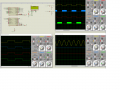
I guess my Half-Bridge signals for SMPS Battery Charger, DC-DC Converter (Two switch forward Converter), and Full-Bridge Driver based Inverter are ok.
What do you people say ?
It will be a very efficient Inverter using 15 USD MOSFET (price of one MOSFET).
I need 2x + 2x + 4x MOSFETS.
2x PIC18F46K22 are used. One will drive 2x Half Bridges and LCD. The other one will drive H-Bridge.
My SPWM frequency is 16 KHz and Half-Bridge signals are at 50 KHz.
two switching transformers will be used. One for SMPS Battery charger which will step down 325V DC (obtained from 230V AC after bridge and filter) to 14.6V DC and another is for DC-DC Converter which steps up Battery's 12V DC to 325V DC for H-Bridge's VBUS voltage.
Feedback will be used and constant output voltage will be maintained for different loads.
2x ACS712 30A sensor will be used. One for Battery Current and another for load current sensing.
I have doubt here.
350W, 230V 50 Hz output Inverter.
Irms = P/V = 1.52A
Ipk = 1.52 * 1.4142 = 2.152A
So, I will design the Inverter for 20A max load current.
max say 3A flows through the DC-DC converters secondary winding. Then what will be the current flowing from 12V Battery to primary winding of switching transformer ?
I need to know this to choose the right current sensor for Battery current measurement.

SMPS Battery Charger
DC-DC Converter
Full-Bridge Inverter
It is for a 350W Inverter.
12V 50Ah Battery is used.
Battery charging current is 5A max.
I guess my Half-Bridge signals for SMPS Battery Charger, DC-DC Converter (Two switch forward Converter), and Full-Bridge Driver based Inverter are ok.
What do you people say ?
It will be a very efficient Inverter using 15 USD MOSFET (price of one MOSFET).
I need 2x + 2x + 4x MOSFETS.
2x PIC18F46K22 are used. One will drive 2x Half Bridges and LCD. The other one will drive H-Bridge.
My SPWM frequency is 16 KHz and Half-Bridge signals are at 50 KHz.
two switching transformers will be used. One for SMPS Battery charger which will step down 325V DC (obtained from 230V AC after bridge and filter) to 14.6V DC and another is for DC-DC Converter which steps up Battery's 12V DC to 325V DC for H-Bridge's VBUS voltage.
Feedback will be used and constant output voltage will be maintained for different loads.
2x ACS712 30A sensor will be used. One for Battery Current and another for load current sensing.
I have doubt here.
350W, 230V 50 Hz output Inverter.
Irms = P/V = 1.52A
Ipk = 1.52 * 1.4142 = 2.152A
So, I will design the Inverter for 20A max load current.
max say 3A flows through the DC-DC converters secondary winding. Then what will be the current flowing from 12V Battery to primary winding of switching transformer ?
I need to know this to choose the right current sensor for Battery current measurement.
Attachments
-
 434.3 KB Views: 20
Last edited:


